EasyManua.ls Logo

Sony FH-411R User Manual

Sony FH-411R
31 pages
To Next Page IconTo Next Page
Page #1 background imageLoading...
Page #1 background image
FH-4T
IR
SERVICE
MANUAL
AEP
Model
E
Model
Australian
Model
@FH-411R
is
composed
of
following
models.
As
for
the
PARTS
LIST
service
manual
it
is
issued
for
each
component
model,
NOTE:
then
plese
refer
to
it.
e
|tems
marked
‘“*"
are
not
stocked
since
they
are
seldom
required
for
routine
COMPONENT
MODEL
NAME
FOR
FH-411R
service.
Some
delay
should
be
antici-
pated
when
ordering
these
items.
TUNER,
DECK,
AMPLIFIER
HST-H411
G
:
Germany
model
EE
:
East
European
model
SPEAKER
SS-H311
IT
>
Italian
model
AUS
:
Australian
model
EA
:
Saudi
Arabia
mode!
ACCESSORY
&
PACKING
MATERIAL
SPECIFICATIONS
1-465-249-11
REMOTE
COMMANDER
(RM-S190)
2-181-754-01
COVER,
BATTERY(for
RM-S190)
Power
requirements
AEP,G,IT,EE
model
:
1-501-349-11
ANTENNA,
LOOP
220V
AC,
50/60Hz
A1-569-007-11
(EE).
ccc
cnn
eee
en
eee
ADAPTOR,
CONVERSION
2P
‘E,EA,AUS
model
:
A\1-569-008-11
(AUS,
EA)...
eee
cee
ADAPTOR,
CONVERSION
2P
110—120V
or
220—240V
AC
3-752-778-11
(AEP,E,EA,AUS)......
MANUAL
INSTRUCTION
adjustable
50/60Hz
(English,French,
Spanish,
Chinese)
:
3-752-778-41
(AEP,G,IT).......00.
MANUAL
INSTRUCTION
Power
consumption
65watts
(German,
Dutch,
Swedish,
Italian,
Portuguese.)
Dimensions
Approx.
595X270X250mm
(w/h/d)
3-752-778-51
(EE).
sete
eee
e
een
es
»
MANUAL
INSTRUCTION
;
(English,
German,
Polish,
Russian)
(231%
Xx
10%
X
10
inches)
fal
Jereised
#4-942-341-01
(EEA).
.seeceeeee
eas
INDIVIDUAL
CARTON
ete
Pree
Ung
Patt
aan
centos
4-942-344-01
(AEP,G,IT,EE,
AUS)...
INDIVIDUAL
CARTON
Weight
Approx.
9.5kg
(20
lb
15
oz)
net
*
4-942-340-01
CUSHION(HST)
Supplied
accessories
RM-S190
Remote
commander
(1)
*
4-857-137-01
CUSHION
(SPEAKER
)
SONY
SUM-3
(NS)
batteries
(2)
poue
COMPACT
HI-DENSITY
Design
and
specifications
subject
to
change
without
notice.
Note:
The
component
identified
by
mark
A
or
dotted
COMPONENT
SYSTEM
SONY.
English
91A1860-1
.
Printed
in
Japan
Sony
Corporation
©1991.
1
9-956-201-11
Audio
Group
Published
by
Customer
Relations
and
service
Group
line
with
mark
A
are
critical
for
safety.
Replace
only
with
part
number
specified.
Question and Answer IconNeed help?

Do you have a question about the Sony FH-411R and is the answer not in the manual?

Sony FH-411R Specifications

General IconGeneral
Speaker Configuration2-Way
CD PlayerYes
BluetoothNo
RadioYes
USB PortNo
Tuner BandsFM, AM

Summary

Specifications

Tuner Section

Detailed specifications for the FM/AM tuner, including tuning ranges and intermediate frequencies.

Amplifier Section

Specifications for the audio amplifier output, inputs, and power requirements.

Cassette Deck Section

Specifications for the cassette tape recording and playback, including frequency response and wow/flutter.

Speaker Section

Specifications for the speaker system, including impedance, sensitivity, and dimensions.

Parts List

Accessory and Packing Material

List of accessories and packing materials included with the unit.

Section 1 General

Overview

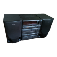
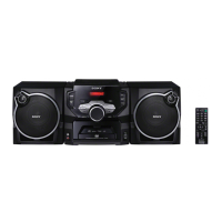
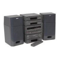
General overview of the FH-411R system components and features.

Model Identification

Information on identifying the specific model based on labels.

Precautions and Preparations

Operating Voltage and Safety Notes

Check and set correct voltage, plus critical safety guidelines.

System Setup and Installation

Steps for preparing and installing the stereo system.

Section 2 Disassembly

Case Removal

Procedure for removing the outer case of the unit.

Section 3 Mechanical Adjustment

Adjustment Precautions and Torque Measurement

Precautions and torque specifications for mechanical adjustments.

Section 4 Electrical Adjustment

Head Azimuth and Tape Speed

Adjusting head azimuth and checking tape speed for optimal performance.

Playback and Record Adjustments

Adjusting playback levels and record bias current for sound quality.

FM/AM Section Tuning and Alignment

Procedures for FM/AM alignment, tuning, and voltage adjustments.

Section 5 Diagrams

Semiconductor and Board Layouts

Diagrams for semiconductor pinouts and circuit board locations.

Printed Wiring and Schematic Diagrams

Layouts of printed wiring and detailed circuit schematics.

Section 6 Exploded Views

Front Panel and Case Assembly

Exploded view of the front panel and main case components.

Cassette Deck Mechanism Assembly

Exploded views of the cassette deck mechanisms.

Section 7 Electrical Parts List

Section-Specific Parts Lists

Parts lists for Control, Power Amp, Dolby SW, Power Supply, Lamp, Volume, LED sections.

Main Section Parts List

List of electrical parts for the main system components.

Related product manuals