Do you have a question about the Sony FH-G50 and is the answer not in the manual?
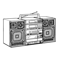
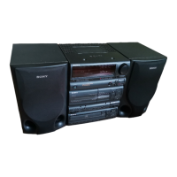
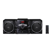
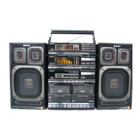
Lists FH-G50, MHC-501, MHC-S200 models covered by the service manual.
Covers abbreviations, general specifications, and accessory parts.
Details specifications for the CD player, tuner, and tape deck sections.
Covers amplifier and speaker system specifications, including power requirements.
Outlines safety checks and AC leakage testing procedures.
Notes on handling optical pick-up blocks, laser diodes, and flexible boards.
Description of front panel, tuner, and amplifier controls and indicators.
Details tape player controls, remote functions, and rear panel connections.
Steps for removing the CD mechanism and front panel.
Steps to remove the TC (Tape Cassette) mechanism.
Procedures for mechanical adjustments including torque measurement.
Procedure for adjusting head azimuth in the deck section.
Procedures for adjusting tape speed and playback level.
Procedures for adjusting record bias and record level.
Covers adjustments for AM, FM, and SW tuner bands.
Procedures for CD focus bias, RF level, S-curve, and E-F balance.
Waveform observation and notes on focus/tracking gain adjustment.
Explains the pin functions for IC101 (TMP87CP64F-6254).
Explains the pin functions for IC501 (CXP82612-0060).
Provides final pin details for IC501.
Shows the schematic of the optical pick-up block.
Shows the main section block diagram and semiconductor lead layouts.
Identifies circuit board locations and Main Section Printed Wiring Boards.
Provides the schematic for the main section and waveform examples.
Shows the schematic and Printed Wiring Boards for the panel section.
Shows block diagrams for multiple integrated circuits.
Explains the pin functions and details for IC101 and IC102.
Shows an exploded view of the chassis section components.
Shows an exploded view of the front panel section components.
Shows an exploded view of the mechanism deck section, part 1.
Shows an exploded view of the mechanism deck section, part 2.
Shows an exploded view of the mechanism deck section, part 3.
Shows an exploded view of the CD mechanism section components.
Shows an exploded view of the base unit section components.
Lists capacitor part numbers and specifications.
Lists resistor and variable resistor part numbers and specifications.
Lists switch, IC, and transistor part numbers and specifications.
Lists additional capacitor part numbers and specifications.
Lists further capacitor part numbers and specifications.
Lists connector and transistor part numbers and specifications.
Lists IC and transistor part numbers and specifications.
Lists transistor and resistor part numbers and specifications.
Lists additional resistor part numbers and specifications.
Lists resistor, variable resistor, and relay components.
Lists coil, connector, and capacitor components.
Lists capacitor, connector, IC, and resistor components.
Lists capacitor, diode, IC, and transistor components.
Lists transistor and miscellaneous components.
Lists final accessories and packing materials.
Lists hardware components used in the system.
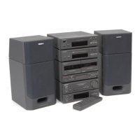
Lists associated system models and speaker system specifications.
Shows an exploded view of the speaker system components.
Lists the parts for the speaker system.
Details the specifications for the SS-H701 speaker unit.
Lists the parts for the SS-H701 speaker system.
| Brand | Sony |
|---|---|
| Model | FH-G50 |
| Category | Stereo System |
| Language | English |