EasyManua.ls Logo

Sony FH-215R Service Manual

Sony FH-215R
58 pages
To Next Page IconTo Next Page
Page #1 background imageLoading...
Page #1 background image
SERVICE
MANUAL
=
vee
ais
FH-1215CD:
UK
Model
‘Dolby’
and
the
double-D
symbo!
are
the
trade
marks
of
Dolby
laboratories
Licensing
Corporation.
Noise
reduction
e
FH-215R
consists
of
ST-215,
TA-215,
TC-215R,
APM-215.
system
manufactured
under
license
from
Dolby
Laboratories
@FH-1215CD
consists
of
ST-215,
TA-215,
TC-215R,
CDP-
Licensing
Corporation.
17F.
CONTENTS
FH-215R/1215CD
ST-215|
(AEP,
UK
Model)
Page
Page
MODEL
IDENTIFICATIONS
............
3
NOTE
ON
LITHIUM
BATTERY
SPECIFICATION
............00
000s
4
NOTE
ON
CERAMIC
FILTER
(CF101,
102)
FEATURES:
sics
iod
Scene
8%
Bod are
eee
de
5
REPLACEMENT
AND
DIODE
D314,
315
NOTE
ON
LITHIUM
BATTERY
.........
5
CONNECTION
...........
00
ce
eee
ST-1
CONNECTOR’S
SIGNAL
ASSIGNMENT
...
6
SECTION
1
ADJUSTMENTS
...........
ST-2
FUNCTION
OF
CONTROLS
............
7
SECTION
2
DIAGRAMS
..............
ST-5
EXPLODED
VIEW
AND
PARTS
LIST
.....
10
2-1.
MOUNTING
DIAGRAM......
ST-5
2-2.
SCHEMATIC
DIAGRAM
.....
ST-7
SECTION
3
EXPLODED
VIEW
AND
See
CDP-17F
SERVICE
MANUAL
Separately
PARTS
LIST
............
ST-11
issued
for
the
information
of
CDP-17F.
~—
Continued
on
page
2
SAFETY-RELATED
COMPONENT
WARNING!!
COMPONENTS
IDENTIFIED
BY
SHADING
AND
MARK
A
ON
THE
SCHEMATIC
DIAGRAMS
AND
IN
THE
PARTS
LIST
ARE
CRITICAL
TO
SAFE
OPERATION.
REPLACE
THESE
COMPONENTS
WITH
SONY
PARTS
COMPACT
HI-DENSITY
WHOSE
PART
NUMBERS
APPEAR
AS
SHOWN
IN
THIS
MANUAL
OR
IN
SUPPLEMENTS
PUBLISHED
BY
SONY.
COM
P
0
N
F
NT
SYSTEM
of
Ld
guess
eel
:
MICROFILM
Question and Answer IconNeed help?

Do you have a question about the Sony FH-215R and is the answer not in the manual?

Sony FH-215R Specifications

General IconGeneral
BrandSony
ModelFH-215R
CategoryStereo System
LanguageEnglish

Summary

Service Manual Overview

Model Identification

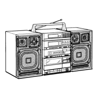
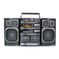
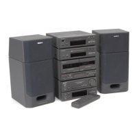
Identifies the FH-215R/FH-1215CD models and their regional variants.

Safety Warnings

Safety-Related Component Warning

Critical components identified by shading/mark A require specific Sony parts for safe operation.

Model Identification Details

TA-215 Identification

Details of TA-215 integrated stereo amplifier label and model variations.

APM-215 Identification

Details of APM-215 speaker system label and model variations.

ST-215 Identification

Details of ST-215 FM stereo/FM-AM tuner label and frequency range.

Component Specifications

ST-215 Tuner Specifications

Technical specifications for the ST-215 FM/AM tuner section.

TC-215R Cassette Deck Specifications

Technical specifications for the TC-215R cassette deck.

TA-215 Amplifier Specifications

Technical specifications for the TA-215 integrated stereo amplifier.

APM-215 Speaker Specifications

Technical specifications for the APM-215 speaker system.

System Features

Tuner, Amplifier, and Cassette Deck Features

Highlights features of the tuner, amplifier, and cassette deck sections.

Lithium Battery Precautions

Lithium Battery Handling Warning

Warning about risk of explosion for lithium batteries during replacement.

Connector Signal Assignments

Function of Controls

Tuner and Amplifier Controls

Description of the controls and indicators for the tuner and amplifier sections.

Cassette Deck Controls and Displays

Remote Commander Operation

Remote Commander Functions and Usage

Explains remote functions, battery installation, and system operation.

Exploded Views and Parts Lists

ST-215 Exploded View and Parts List

Exploded view and parts list for the ST-215 component.

Accessory and Packing Material Parts

Parts list for accessories and packing materials.

ST-215 FM Tuner Notes

Ceramic Filter and Diode Connection

Note on ceramic filter replacement and diode connection for FM IF offset adjustment.

ST-215 FM Section Adjustments

FM Tracking and Discriminator Alignment

Procedures for FM tracking adjustment and discriminator alignment.

FM OSC Voltage and Tuned Indication Adjustments

Procedures for adjusting FM OSC voltage and tuned indication lighting.

ST-215 AM/MW/LW/SW Section Adjustments

MW/LW and SW Tracking/OSC Adjustments

Procedures for MW/LW/SW tracking and OSC voltage adjustments.

ST-215 Diagrams

Mounting Diagram and Semiconductor Locations

Diagram showing component mounting and semiconductor locations on the main board.

ST-215 Schematic Diagram

ST-215 Exploded View and Parts List

Exploded View and Mechanical Parts

Exploded view and list of mechanical parts for the ST-215.

Electrical Parts List

Comprehensive list of all electrical components used in the ST-215.

TA-215 Amplifier IC Block Diagrams

IC Block Diagrams

Block diagrams for ICs used in the TA-215 amplifier.

TA-215 Semiconductor Information

Semiconductor Lead Layouts

Diagrams showing lead layouts for various semiconductors.

TA-215 Mounting and Diagram

Semiconductor Locations and Mounting Diagram

Map showing semiconductor locations and component mounting.

TA-215 Schematic Diagrams

Board Schematic Diagrams

Schematic diagrams for GEQ, Power, and other boards.

TA-215 Exploded Views and Parts Lists

Mechanical Exploded Views and Parts Lists

Exploded views and lists of mechanical parts for the TA-215.

Electrical Parts List

Comprehensive list of all electrical components used in the TA-215.

TC-215R Cassette Deck

Mechanism Information

Information about similar mechanisms and tape transport type.

TC-215R Servicing Outline

Servicing Precautions

Precautions to be taken during servicing of the TC-215R.

TC-215R Adjustments

Mechanical Adjustments

Procedures for mechanical adjustments including torque measurements.

Electrical Adjustments Overview

Overview of electrical adjustment procedures and check points.

Tape Speed, Azimuth, Playback, and Bias Adjustments

Procedures for tape speed, head azimuth, playback level, and bias adjustments.

TC-215R Diagrams

Mounting and Block Diagrams

Diagrams showing component mounting and IC block diagrams.

Schematic Diagrams

Schematic diagrams for the main board and associated boards.

TC-215R Exploded Views and Parts Lists

Mechanical Exploded Views and Parts Lists

Exploded views and lists of mechanical parts for the TC-215R.

Electrical Parts List

Comprehensive list of all electrical components used in the TC-215R.

APM-215 Speaker System

Disassembly and Wiring Diagram

Instructions for front panel removal and speaker wiring diagram.

APM-215 Exploded View and Parts List

Exploded View and Mechanical Parts

Exploded view and list of mechanical parts for the APM-215.

Electrical Parts and Accessories

Lists of electrical parts, cords, and accessories for APM-215.

Related product manuals