Do you have a question about the Sony GV-A500 and is the answer not in the manual?
General specifications including power requirements, consumption, and output.
Details about AC power adapter, including input, output, application, and specifications.
Warning about replacing components identified by mark ! or dotted line for safe operation.
Explains the 4-digit display indicating error codes and how to interpret them.
Describes how to access and view past self-diagnosis codes.
Lists self-diagnosis codes, symptoms, and corresponding corrections.
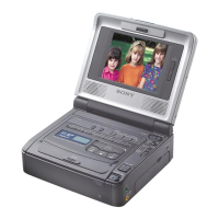
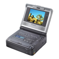
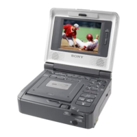
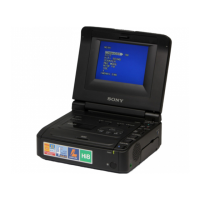
Instructions for starting and using the manual, checking accessories, and basic operations.
Steps for installing power, inserting, and playing cassettes.
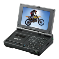
Explains advanced functions like watching on TV and editing tapes.
Covers battery charging, cassette types, maintenance, and international use.
Procedure for removing the cassette lid assembly.
Procedure for removing the LCD cabinet.
Steps for disassembling the crystal indication module and PD-88 board.
Procedure for removing the bottom cabinet assembly.
Procedure for disassembling the MD block assembly.
Steps for disassembling the FK-71 switch block and DD-100 board.
Procedure for disassembling the VC-197 board.
Steps for disassembling the B mechanism deck.
Procedure for removing the right cabinet and FP-571 board.
Steps for disassembling the EX-34 board.
Disassembly steps for multiple boards and the speaker.
Procedure for removing the upper cabinet assembly.
Diagram showing the location of various circuit boards within the unit.
A comprehensive block diagram illustrating the entire system architecture and component interconnections.
Illustrates the video signal processing path, focusing on specific components and signal flows.
Continues the video signal path illustration, detailing further processing and interconnections.
Details the servo system control, including motor drives and feedback loops.
Illustrates the main system control logic, interfaces, and data flow.
Shows the audio signal processing paths and related components.
Details the logic for controlling operational modes and user interface functions.
Illustrates the signal flow and components related to the LCD display system.
Shows the power distribution and regulation circuits throughout the unit.
Lists required service tools and preliminary steps before performing any adjustments.
Details the specific tools required for various adjustment procedures.
Explains the usage and precautions for the remote commander used in adjustments.
Contains detailed tables for Page D, F, and E addresses and their initial/adjustment values.
Procedures for mechanical adjustments, including tape path and without cassette operation.
Steps for adjusting video signals, frequency, levels, and color parameters.
Details how to enter and use the service mode for diagnostics and specific adjustments.
Procedures for adjusting system control parameters like page data and battery voltage.
Adjustments related to servo systems, including FG offset and switching position.
Procedures for adjusting IR transmitter video and audio signals.
Adjustments for audio system performance, including deviation and BPF.
Calibration procedures for the LCD display, including VCO, H POS, Brightness, and Color.
Provides visual breakdowns of major assemblies for part identification.
Lists parts for the outer cabinet assembly.
Lists parts for the LCD and upper cabinet assemblies.
Lists parts for the MD block assembly.
Lists parts for the cassette compartment block section.
Lists parts for the LS chassis block section.
Lists parts for the mechanism chassis block.
Lists electrical components such as capacitors, resistors, ICs, and diodes.
Lists accessories, packing materials, and other items.