Do you have a question about the Sony GV-D1000 and is the answer not in the manual?
Details the video and audio recording systems, tape specifications, and operational times.
Enumerate all input and output connector types, including signal levels and impedance.
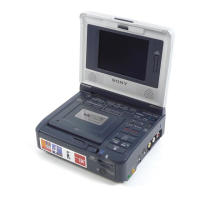
Specifies the LCD screen's physical dimensions, resolution, and picture details.
Outlines general operational parameters like power, environment, dimensions, and mass.
Provides specifications for the AC power adapter, including voltage, current, and operating conditions.
Lists required tools and precautions before starting any adjustments.
Covers procedures for entering record/playback modes and tape path adjustments.
Details preparation, initialization, and adjustment procedures for various electrical systems.
Covers serial number input and company ID input procedures.
Explains adjustments for Capstan FG duty, PLL, AGC, APC, and AEQ levels.
Outlines procedures for origin oscillation and chroma BPF adjustments.
Details checks for playback level, distortion, noise, and separation.
Covers initial data input, VCO, RGB AMP, Contrast, COM AMP, V-COM, White Balance.
Explains how to use the adjustment remote commander and data processing for service mode.
Details methods to maintain power supply during repair procedures to prevent unit shutdown.
Provides steps for forcibly ejecting a cassette when the unit's eject function fails.
Details the procedure for removing the main LCD cabinet assembly from the unit.
Instructions for removing the PD-130 and LS-56 boards, including harness and screw details.
Illustrates the physical layout and names of all major circuit boards within the unit.
Depicts the placement of various flexible circuit boards within the device chassis.
Provides the first part of the overall frame schematic diagram, detailing interconnections.
Presents the second part of the overall frame schematic diagram, completing the interconnections.
Schematic diagrams for the PD-130 board, detailing LCD driver and backlight functions.
Comprehensive schematic diagrams for the VC-275 board, covering multiple functional blocks.
Schematic diagram for the FK-81 board, focusing on the switch block functions.
Schematic diagram for the EX-39 board, detailing the multi-connector functionality.
Presents the overall system block diagrams, illustrating the main functional interconnections.
Illustrates the power block diagrams, showing power supply and distribution paths.
Printed wiring board layout for the FK-81 board, detailing the switch block components.
Printed wiring board layouts for the PD-130 board, showing LCD driver and backlight circuitry.
Printed wiring board layout for the LS-56 board, focusing on the LCD switch components.
Printed wiring board layouts for the EX-39 board, illustrating the multi-connector components.
Printed wiring board layouts for the IO-69 board, detailing AV input/output and remote receiver.
Printed wiring board layouts for the VC-275 board, covering various functional blocks and interconnections.
Printed wiring board layouts for the PR-41 board, showing the remote commander receiver components.
Illustrates typical waveforms for IC5501 and IC5502 on the PD-130 board for signal analysis.
Illustrates the physical location of components mounted on the FK-81 board for identification.
Depicts the physical placement of components on the PD-130 board, aiding in component identification.
Illustrates the physical location of components mounted on the VC-275 board, crucial for repair and assembly.