5-31
2-4. TAPE PATH ADJUSTMENT
2-4-1. Preparations for Adjustment
1) Clean the tape path face (tape guide, drum, capstan shaft, pinch
roller).
2) Connect the adjustment remote commander.
3) Turn on the HOLD switch of the adjustment remote
commander.
4) Select page: 3, address: 33, and set data: 08.
5) Connect the oscilloscope to CPC jig for BX/BK.
Channel 1: PB RF (MON)
Channel 2: SWP
Note: Connect a 75Ω resistor between the test point PB RF (MON)
and GND.
75Ω resistor (Parts code: 1-247-804-11)
6) Playback the SW/OL standard tape. (WR5-2D)
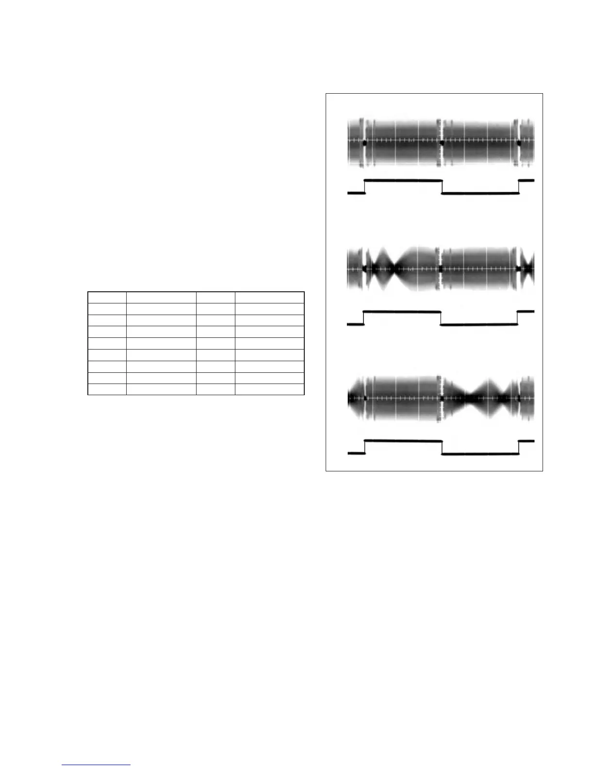
7) Check that the oscilloscope RF waveform is flat at the entrance
and exit.
If not flat, perform the following section 2-4-2. until it is flat.
8) Perform “Processing after operations”, after completing
adjustment.
Test point of CPC jig for BX/BK
Note: Pin No. are those of CN1011 of VC-256 board.
Table 5-2-1.
[Processing after operations]
1) Connect the adjustment remote commander, and turn on the
HOLD switch.
2) Select page: 3, address: 33, and set data: 00.
3) Remove the power supply from the unit.
Fig. 5-2-2.
Pin No.
3
7
9
13
17
20
16
8
Signal Name
BL
EVF VG
PB RF (MON)
BPF MONI
TMS
TDI
SWP
CAP FG
Pin No.
1
5
10
15
19
18
14
Signal Name
EVF VCO
BL 4.75
GND
REC RF (RF IN)
TDO
TCK
IR VIDEO
CH1
Normal
CH2
CH1
Entrance side faulty
CH2
CH1
Exit side faulty
CH2
 Loading...