Do you have a question about the Sony Handycam Video 8 CCD-TR606E and is the answer not in the manual?
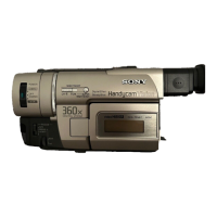
Details about recording system, cassette, tape speed, and time.
Specifies light sensitivity, color temperature, and output jack specifications.
Details power sources, operating voltage, and consumption.
Critical safety procedures to perform after completing repairs.
Highlights critical components that require specific replacement parts for safety.
Instructions for charging, installing, and using battery packs for optimal performance.
Covers core camera operations like recording, zoom, and steady shot features.
Details alternative power sources and selection of adjustment modes.
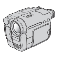
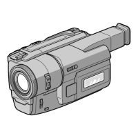
Identifies buttons, switches, dials, ports, and indicators on the camcorder.
Diagrams showing internal layout and external features like tripod receptacles.
Identifies remote commander buttons and explains accessory attachment.
Explains indicators for battery level, tape end, and tape insertion status.
Covers indicators for video head contamination, lithium battery issues, and general errors.
Steps for removing the front panel, cassette lid, and left/right cabinets.
Instructions for removing various boards and assemblies like the lens.
Diagrams showing the internal layout and location of key components.
Diagrams showing the physical location of various circuit boards within the camcorder.
Overall system schematic showing main blocks and interconnections.
Layouts for various boards like JK-98, SW-222, and MF-213 boards.
Circuit diagrams for SL-32, FP-442, LM-40, and LS-33 boards.
Exploded views for cabinets, main boards, and mechanism assemblies.
Exploded view and parts list for the zoom lens unit.
Lists electrical components for AU-149, CD-105, DD-55, and other boards.
Lists required tools, precautions, remote commander usage, and data tables.
Points requiring adjustment after replacing CCD imager or lens block.
Voltage checks and procedures for initializing/modifying page F data.
Procedures for 28 MHz oscillation, Hall adjustment, and other specific tasks.
Adjusting horizontal slant, centering, and focus for EVF display.
Adjusting vertical amplitude, brightness, contrast, and oscillation frequency.
Steps to adjust color reproduction using color bar signals and vectorscope.
Diagrams showing locations of adjustment points on DD-55 and VC-132 boards.
Layout diagram showing adjustment points for the AU-149 board.
Procedure for setting the track shift mode for mechanism adjustments.
Steps for preparing the camcorder and equipment for mechanical adjustments.
Lists required equipment, precautions, and setup for video adjustments.
Procedures for entering service mode and checking basic signals.
Information on alignment tapes and setting the REC mode.
Procedure for adjusting the switching position of the servo system.
Adjusting playback frequency response using alignment tape.
Procedures for checking flying erase and VXO oscillation frequency.
Adjusting the EE level for proper video signal output.
Procedure for adjusting the IR signal for correct video output.
Adjusting the chroma comb filter for optimal color signal clarity.
Adjusting the emphasis input level for proper signal processing.
Adjusting the PB Y signal level for correct playback output.
Adjusting the PB line out signal level for correct playback output.
Adjusting the Y FM deviation for correct video signal processing.
Adjusting the Y FM carrier frequency for accurate video signal.
Adjusting the REC C level for specified amplitude.
Checking the REC ATF signal level against specified value.
Checking REC AFM level and fine-tuning chroma comb filter.
Procedures for checking 1.5 MHz record level and E-E output level.
Adjusting REC matrix L-R/L+R and 1.5/1.7 MHz deviation.
Procedures for checking overall audio characteristics, distortion, separation, and noise.
Explanation of category codes used for accessing RAM and EEPROM data.
Steps for entering and navigating the service mode using the remote commander.
Managing page D write protect, test modes, and emergency codes.
Using tables to discriminate bit values and check emergency modes.
Checking mode controller inputs and white balance mode switching.
Verifying zoom position accuracy and LCD/LED segment functionality.
Verifying functionality of camcorder buttons and A/D port inputs.
Testing wireless remote reception and battery voltage monitoring.
Verifying mechanism switches, and input/output signals of the controller.
Checking A/D port input voltage and tape top/end sensor status.
Procedures for individual motor control and checking microprocessor version.
Procedures for adjusting battery end indicators and performing battery down checks.
| Camcorder Type | Analog |
|---|---|
| Recording Format | Video8 |
| Sensor Type | CCD |
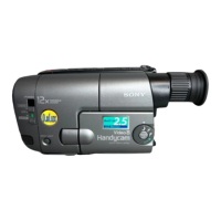
| Optical Zoom | 12x |
| Digital Zoom | 24x |
| Viewfinder Type | Electronic |
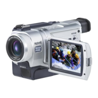
| Screen Size | 2.5 inches |
| LCD Screen | Yes |
| Viewfinder | Yes |
| Microphone | Built-in |