HCD-GTZ2/GTZ2i/GTZ3/GTZ3i
4
SECTION 2
DISASSEMBLY
• This set can be disassembled in the order shown below.
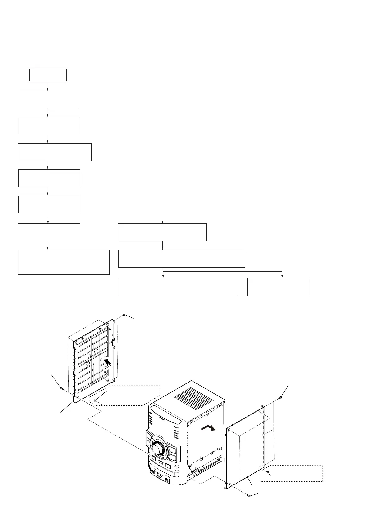
2-1. DISASSEMBLY FLOW
2-2. CASE (SIDE-L/R)
(Page 4)
2-3. TOP CASE
(Page 5)
2-4. FRONT PANEL BLOCK
(Page 5)
2-5. DC FAN (M101)
(Page 6)
2-6. BACK PANEL
(Page 6)
2-7. MAIN BOARD
(Page 7)
2-9. HUB BOARD, DMB19 BOARD
(Page 8)
2-8. DC FAN (M102) (GTZ3/GTZ3i),
POWER AMP BOARD
(Page 7)
2-10. CD MECHANISM BLOCK (CDM88B-DVBU101)
(Page 8)
2-11. OPTICAL PICK-UP BLOCK (KHM-313CAB)
(Page 9)
SET
2-12. BELT (DLM3A)
(Page 9)
Note: Follow the disassembly procedure in the numerical order given.
2-2. CASE (SIDE-L/R)
(Mexican)
(Mexican)
2 three screws
(BVTP3 u 8)
2 three screws
(BVTP3 u 8)
4 case (side-L)
4 case (side-R)
1 three screws
(case 3 TP2)
1 screw (case 3 TP2)
1 three screws
(case 3 TP2)
1 screw (case 3 TP2)
3
3
Ver. 1.1