EasyManua.ls Logo

Sony HCD-H170 - Tape Speed and Playback Level Adjustment

Sony HCD-H170
91 pages
Print Icon
To Next Page IconTo Next Page
To Previous Page IconTo Previous Page
Loading...
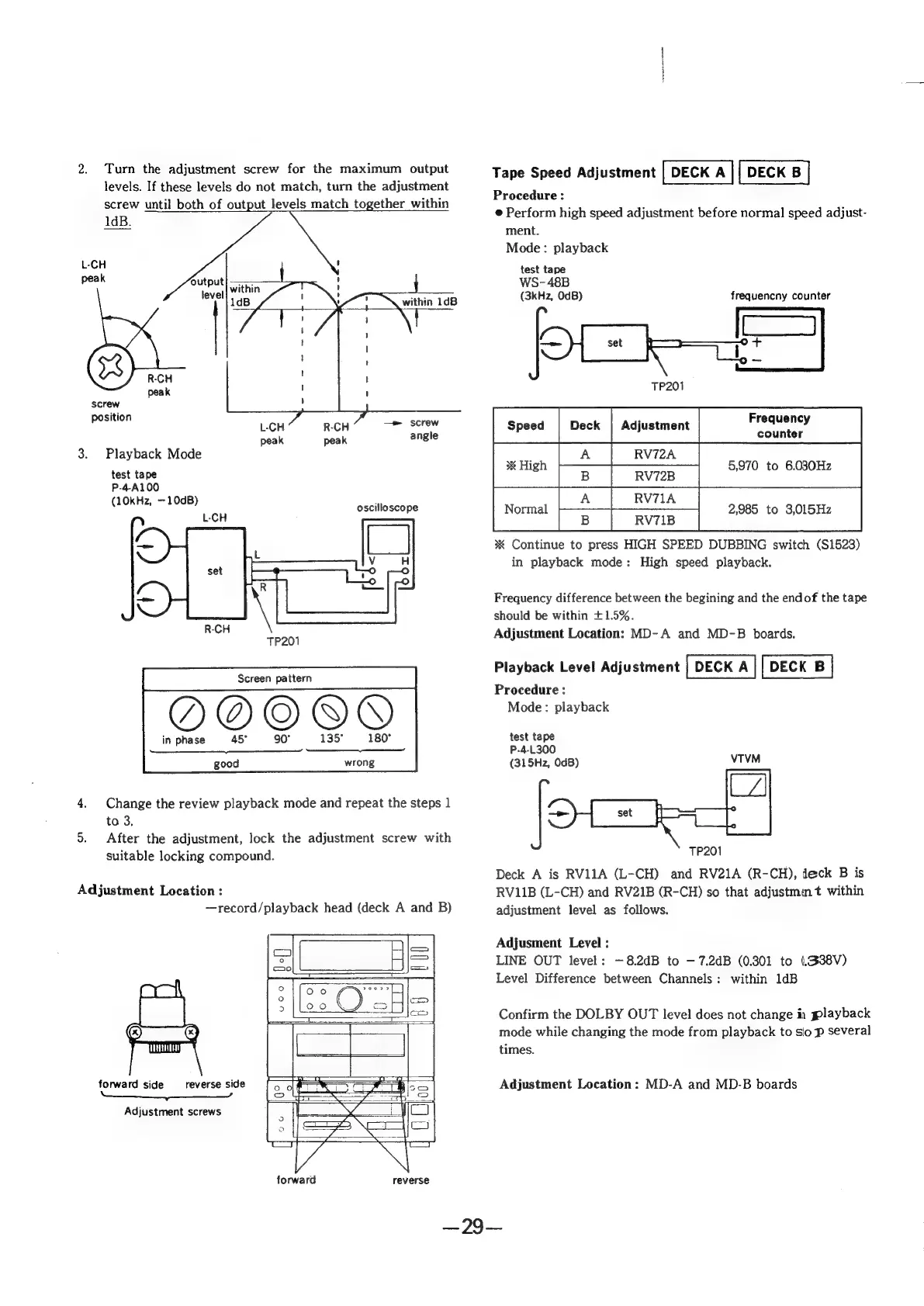
2.
Turn
the
adjustment
screw
for
the
maximum
output
levels.
If
these
levels
do
not
match,
turn
the
adjustment
screw
until
both
of
output
levels
match
together
within
1dB.
L-CH
peak
within
1dB
R-CH
peak
screw
pesten
L-CH
R-CH
Pe
SCO
peak
peak
angle
3.
Playback
Mode
test
tape
P-4-A100
(10kHz,
—10dB)
:
oscilloscope
L-CH
TP201
Screen
pattern
ane
OQOOO@PY
in
phase
45°
135°
180°
ed
good
wrong
4.
Change
the
review
playback
mode
and
repeat
the
steps
1
to
3,
5.
After
the
adjustment,
lock
the
adjustment
screw
with
suitable
locking
compound.
Adjustment
Location
:
—record/playback
head
(deck
A
and
B)
forward
side
reverse
side
Adjustment
screws
forward
reverse
Tape
Speed
Adjustment
Procedure
:
e@
Perform
high
speed
adjustment
before
normal
speed
adjust-
ment.
Mode:
playback
test
tape
WS-48B
(3kHz,
OdB)
frequencny
counter
counter
RV72A
*
High
5,970
to
6.030Hz
B
|
RV72B
|
A
era
Normal
2,985
to
3,015Hz
B
|
RV71B
x
Continue
to
press
HIGH
SPEED
DUBBING
switch
(S1523)
in
playback
mode:
High
speed
playback.
Frequency
difference
between
the
begining
and
the
endof
the
tape
should
be
within
+1.5%.
Adjustment
Location:
MD-
A
and
MD-B
boards.
Playback
Level
Adjustment
Procedure
:
Mode:
playback
test
tape
P-4-L300
(315Hz,
0dB)
VTVM
TP201
Deck
A
is
RV11A
(L-CH)
and
RV21A
(R-CH),
deck
B
is
RV11B
(L-CH)
and
RV21B
(R-CH)
so
that
adjustmm
t
within
adjustment
level
as
follows.
Adjusment
Level
:
LINE
OUT
level:
—8.2dB
to
—7.2dB
(0.301
to
(.338V)
Level
Difference
between
Channels:
within
1dB
Confirm
the
DOLBY
OUT
level
does
not
change
in
playback
mode
while
changing
the
mode
from
playback
to
sio
p
several
times.
Adjustment
Location:
MD-A
and
MD-B
boards
290s