SERVICE MANUAL
Sony Corporation
Audio Business Group
Published by Sony Techno Create Corporation
SPECIFICATIONS
DVD RECEIVER
9-887-987-02
2008E05-1
©
2008.05
US Model
HCD-HDX275/HDX277WC/
HDX279W/HDX576WF
Canadian Model
HCD-HDX475/HDX576WF/HDX675
E Model
Australian Model
HCD-HDX275
Ver. 1.1 2008.05
Model Name Using Similar Mechanism HCD-HDX265
DVD Mechanism Type CDM81C-DVBU101
Optical Pick-up Block Name
KHM-310CAB or
KHM-313CAB
• HCD-HDX275 is the amplifier section, super
audio CD/DVD system, tuner section and
video section in DAV-HDX275.
• HCD-HDX277WC is the amplifier section,
super audio CD/DVD system, tuner section
and video section in DAV-HDX277WC.
• HCD-HDX279W is the amplifier section,
super audio CD/DVD system, tuner section
and video section in DAV-HDX279W.
• HCD-HDX475 is the amplifier section, super
audio CD/DVD system, tuner section and
video section in DAV-HDX475.
• HCD-HDX576WF is the amplifier section,
super audio CD/DVD system, tuner section
and video section in DAV-HDX576WF.
• HCD-HDX675 is the amplifier section, super
audio CD/DVD system, tuner section and
video section in DAV-HDX675.
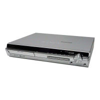
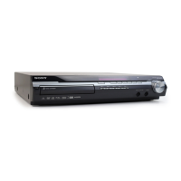
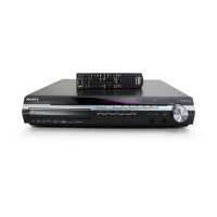
HCD-HDX275/HDX277WC/HDX279W/
HDX475/HDX576WF/HDX675
Photo: HCD-HDX275
– Continued on next page –
This product incorporates copyright protection technology that is
protected by U.S. patents and other intellectual property rights.
Use of this copyright protection technology must be authorized by
Macrovision, and is intended for home and other limited viewing
uses only unless otherwise authorized by Macrovision. Reverse
engineering or disassembly is prohibited.
This system incorporates with Dolby* Digital and Dolby Pro Log-
ic (II) adaptive matrix surround decoder and the DTS** Digital
Surround System.
* Manufactured under license from Dolby Laboratories.
“Dolby”, “Pro Logic”, and the double-D symbol are trade-
marks of Dolby Laboratories.
** Manufactured under license from DTS, Inc.
“DTS” and “DTS Digital Surround” are registered trademarks
of DTS, Inc.
This system incorporates High-Defi nition Multimedia Interface
(HDMITM) technology.
HDMI, the HDMI logo and High-Defi nition Multimedia Interface
are trademarks or registered trademarks of HDMI Licensing LLC.
“BRAVIA” and are trademarks of Sony Corpora-
tion.
“S-AIR” and its logo are trademarks of Sony Corporation.
AUDIO POWER SPECIFICATIONS
for the US model
POWER OUTPUT AND TOTAL HARMONIC
DISTORTION:
With 3 ohms loads, both channels
driven, from 180 - 20,000 Hz; rated
84 watts per channel minimum
RMS power, with no more than
0.7% total harmonic distortion from
250 milli watts to rated output.
Amplifi er Section (EXCEPT HCD-HDX279W/HDX576WF)
Surround mode (reference) RMS output power
FL/FR/C/SL/SR*: 143 watts (per
channel at 3 ohms, 1 kHz, 10%
THD)
Subwoofer*: 285 watts (at 1.5
ohms, 80 Hz, 10% THD)
Amplifi er Section (HCD-HDX279W/HDX576WF)
Surround mode (reference) RMS output power
FL/FR/C*: 143 watts (per channel
at 3 ohms, 1 kHz, 10% THD)
Subwoofer*: 285 watts (at 1.5
ohms, 80 Hz, 10% THD)
* Depending on the decoding mode settings and the source,
there may be no sound output.
Inputs (Analog)
TV/VIDEO (AUDIO IN) (EXCEPT HCD-HDX576WF)
Sensitivity: 450/250 mV
TV (AUDIO IN) (HCD-HDX576WF)
Sensitivity: 450/250 mV
SAT/CABLE (AUDIO IN) (HCD-HDX576WF)
Sensitivity: 450/250 mV
AUDIO IN Sensitivity: 250/125 mV
Inputs (Digital)
TV/VIDEO (COAXIAL IN/OPTICAL IN) (EXCEPT HCD-
HDX576WF) Impedance: 75 ohms/-
TV (COAXIAL IN/OPTICAL IN) (HCD-HDX576WF)
Impedance: 75 ohms/-
Outputs (Analog)
Phones Accepts low- and high-impedance
headphones.
Super Audio CD/DVD System
Laser Semiconductor laser
(Super Audio CD/DVD: λ = 650
nm)
(CD: λ = 790 nm)
Emission duration: continuous
Signalformat system NTSC
Tuner Section
System PLL quartz-locked digital synthe-
sizer
FM tuner section
Tuning range
North American models: 87.5 MHz - 108.0 MHz (100 kHz
step)
Other models: 87.5 MHz - 108.0 MHz (50 kHz
step)
Antenna (aerial) FM wire antenna (aerial)
Antenna (aerial) terminals 75 ohms, unbalanced
Intermediate frequency 10.7 MHz
AM tuner section
Tuning range
North American, Mexican, and Latin American
models:
530kHz - 1,710kHz (with the
interval set at 10kHz)
531kHz - 1,710kHz (with the
interval set at 9kHz)
w
w
w
.
x
i
a
o
y
u
1
6
3
.
c
o
m
Q
Q
3
7
6
3
1
5
1
5
0
9
9
2
8
9
4
2
9
8
T
E
L
1
3
9
4
2
2
9
6
5
1
3
9
9
2
8
9
4
2
9
8
0
5
1
5
1
3
6
7
3
Q
Q
TEL 13942296513 QQ 376315150 892498299
TEL 13942296513 QQ 376315150 892498299
http://www.xiaoyu163.com
http://www.xiaoyu163.com