EasyManua.ls Logo

Sony HCD-SC6 User Manual

Sony HCD-SC6
126 pages
To Next Page IconTo Next Page
Page #1 background imageLoading...
Page #1 background image
HCD-SC5/SC6/SC8
AEP Model
UK Model
E Model
HCD-SC5/SC6/SC8
Australian Model
HCD-SC6/SC8
SERVICE MANUAL
SACD/DVD RECEIVER
Sony Corporation
Home Audio Company
Published by Sony Engineering Corporation
9-961-137-01
2003I1678-1
© 2003.09
HCD-SC5/SC6/SC8 are the amplifier, DVD/
SACD and tuner section in DAV-SC5/SC6/SC8.
Ver 1.0 2003. 09
SPECIFICATIONS
Model Name Using Similar Mechanism NEW
Mechanism Type
CDM80-DVBU24
Optical Pick-up Name
TDP022W
OUT):
Voltage: 1 V
Impedance: 1 kilohm
Phones Accepts low-and high-
impedance headphones.
Super Audio CD/DVD system
Laser Semiconductor laser
(Super Audio CD/DVD: λ
= 650 nm)
(CD: λ = 780 nm)
Emission duration:
continuous
Signal format system NTSC or NTSC/PAL
Frequency response (at 2 CH STEREO mode)
DVD (PCM): 2 Hz to 22
kHz (±1.0 dB)
CD: 2 Hz to 20 kHz (±1.
0
dB)
Harmonic distortion Less than 0.03 %
Outputs VIDEO 1 (AUDIO
VIDEO 1:
Sensitivity: 150 mV
Impedance: 50 kilohms
VIDEO 2:
Sensitivity: 300 mV
Impedance: 50 kilohms
(Other models)
Tuner section
System PLL quartz-locked digital
synthesizer system
FM tuner section
Tuning range 87.5 – 108.0 MHz (50 kHz
step)
Aerial FM wire aerial
Aerial terminals 75 ohms, unbalanced
Intermediate frequency 10.7 MHz
AM tuner section
Aerial AM loop aerial
Intermediate frequency 450 kHz
Vi
(AEP, UK and Russian models)
deo section (VIDEO 1, 2, EURO AV)
Inputs Video: 1 Vp-p 75 ohms
Outputs Video: 1 Vp-p 75 ohms
Amplifier section
Stereo mode 90 W + 90 W (4 ohms at
1 kHz, THD 10 %)
Surround mode Front: 90 W + 90 W
100 W + 100 W (4 ohms
at 1 kHz, THD 10 %)
(HCD-SC6/SC8)
100 W + 100 W (4 ohms
at 1 kHz, THD 10 %)
(HCD-SC6/SC8)
(HCD-SC5)
(HCD-SC5)
(HCD-SC5)
(HCD-SC5)
100 W + 100 W
(HCD-SC6/SC8)
Centre*:
90 W
(HCD-SC6/SC8)
(HCD-SC5/SC6)
100 W
Surround*: 90 W + 90W
(4 ohms at 1 kHz, THD
10 %)
*Depending on the sound field settings and the source,
there may be no sound output.
Inputs VIDEO 1/VIDEO 2/TV:
Sensitivity: 150 mV
Impedance: 50 kilohms
(AEP, UK and Russian
models)
Subwoofer*: 100 W
(4 ohms at 100 Hz, THD
10 %)
Tuning range
AEP, UK, Russian, Australian, Singapore and
Middle Easten models: 531 – 1,602 kHz (with the
interval set at 9 kHz)
Video section (Other models)
Inputs Video: 1 Vp-p 75 ohms
Outputs Video: 1 Vp-p 75 ohms
S video:
Y: 1 Vp-p 75 ohms
C: 0.286 Vp-p 75 ohms
COMPONENT:
Y: 1 Vp-p 75 ohms
P
B/CB, PR/CR: 0.7 Vp-p
75 ohms
General
Power requirements
European models: 230 V AC, 50/60 Hz
Australian and Asian models:
220 – 240 V AC, 50/60 Hz
Taiwan models: 120 V AC, 50/60 Hz
Other models: 110 – 120 V AC, 50/60 Hz
Dimensions (approx.) 380 × 60 × 337 mm (w/h/d)
incl. projecting parts
Mass (approx.) 4.2 kg
Operating temperature 5°C to 35°C (41°F to 95°F)
Operating humidity 5 % to 90 %
Other models: 531 – 1,602 kHz (with the
interval set at 9 kHz)
530 – 1,710 kHz (with the
interval set at 10 kHz)
Design and specification are subject to change without
notice.
PHOTO: HCD-SC5

Table of Contents

Question and Answer IconNeed help?

Do you have a question about the Sony HCD-SC6 and is the answer not in the manual?

Sony HCD-SC6 Specifications

General IconGeneral
Power Output50W per channel (RMS)
TunerFM/AM
CD PlayerYes
BluetoothNo
Dimensions (W x H x D)Main Unit: 280 x 305 x 350 mm, Speakers: 220 x 305 x 220 mm
WeightMain Unit: 6.8 kg, Speakers: 3.2 kg (each)
CD Player TypeSingle Disc
Frequency Response20 Hz - 20 kHz
Speaker Impedance6 Ohms
FunctionsCD, Cassette
TypeMini Hi-Fi Component System

Summary

Specifications Overview

Amplifier Section Specifications

Details output power and impedance for stereo and surround modes.

Surround Mode Specifications

Power output for surround channels, including center and surround.

Subwoofer Output Power

Power output specification for the subwoofer channel.

Audio Input Specifications

Sensitivity and impedance for VIDEO 1, VIDEO 2, and TV inputs.

Video Section Specifications

Input/output levels and impedance for video signals across models.

Tuner Section Specifications

Tuning ranges and intermediate frequencies for FM and AM reception.

General Unit Specifications

Power requirements, dimensions, operating temperature, and humidity.

Servicing Notes

General Information

Front Panel Controls

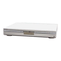
Identifies and describes all controls and indicators on the front panel.

Rear Panel Connections

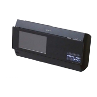
Diagrams illustrating rear panel input/output jacks for different models.

Disassembly Procedures

Front and Side Panel Removal

Step-by-step guide for removing front and side panels.

Mechanism Deck Disassembly

Detailed steps for disassembling the CD/DVD mechanism deck.

Optical Pick-up Removal

Procedure for safely removing the optical pick-up unit.

Lever and Gear Disassembly

Instructions for removing various levers and gears in the mechanism.

Test Modes

Version Display Mode

Displays the unit's software version information.

Key Test Mode

Verifies the functionality of all unit and remote buttons.

Display Test Mode

Tests all segments of the front panel display.

OSD Test Mode

Accesses test menus and diagnostic information via the TV screen.

Disc Slot Lock Function

Enables or disables the disc slot lock for anti-theft.

Repeat Limit Release Mode

Releases the repeat limit function for disc playback.

CDM Ship Mode

Moves the optical pick-up to a vibration-durable position for shipping.

Electrical Adjustments

Auto Servo Adjustment Procedure

Guides servo circuit adjustment after parts replacement.

Diagrams and Schematics

Circuit Boards Location

Visual guide to the placement of all circuit boards within the unit.

RF/Servo Section Block Diagram

Block diagram illustrating signal flow in the RF and servo sections.

Audio (DSP) Section Diagram

Schematic detailing the digital signal processing for audio.

Video Section Schematic

Schematic illustrating the video signal processing path.

Power Supply Section Diagram

Block diagram of the unit's power supply circuitry.

IC Block Diagrams

Block diagrams showing the internal functions of key integrated circuits.

Exploded Views and Parts

Case Section Exploded View

Exploded diagram of the external case components and their assembly.

Front Panel Exploded View

Exploded diagram of the front panel parts and their layout.

Mechanism Deck Exploded Views

Detailed exploded diagrams of the CD/DVD mechanism deck sections.

Base Unit Exploded View

Exploded diagram showing the components of the base unit.

Electrical Parts List

Amplifier Board Parts

Comprehensive list of components for the amplifier board.

Capacitors List

Detailed list of all capacitors with part numbers and specifications.

Resistors List

Detailed list of all resistors with part numbers and specifications.

Related product manuals