Do you have a question about the Sony HDCAM HDW-F900 and is the answer not in the manual?
Manual is for qualified personnel only; follow instructions to avoid shock, fire, injury.
Procedures for high voltage blocks and circuits must be precise and follow manual instructions.
Danger of explosion if battery is incorrectly replaced; use only specified types.
Information on proper disposal of used batteries and compliance with local regulations.
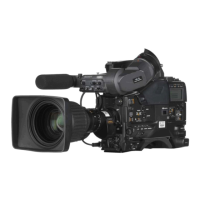
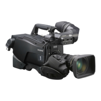
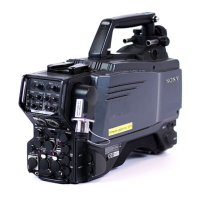
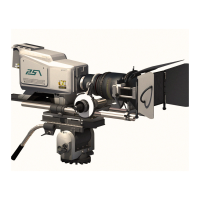
Provides information for installation, maintenance, and primary service of the HDW-F900 camcorder.
Lists additional Sony manuals for operation and maintenance of the HDW-F900 and HDVF-20A.
Verifies ROM versions of peripheral equipment against the camera for proper operation.
Lists all accessories provided with the unit, including manuals and cables.
Specifies temperature, humidity, and location requirements for optimal unit performance.
Details necessary connectors and cables for installation and maintenance work.
Provides specifications for various input and output signal connectors and their pin assignments.
Instructions for cleaning the video head when it becomes clogged, referencing another section.
Essential for understanding the unit's internal layout and component placement.
Details configuration settings for various internal boards using switches and pins.
Step-by-step guide for removing and installing the unit's exterior front lid and panels.
Key procedures for removing and installing various plug-in circuit boards.
Detailed steps for removing and installing the cassette compartment assembly.
Procedure for manually ejecting a cassette tape when normal operations are disabled.
Lists necessary tools and equipment for performing adjustments and maintenance.
Explains warning indicators and lists error codes with their corresponding causes and operating statuses.
Describes error messages superimposed on the viewfinder screen and provides remedies.
Details how to enter and operate the diagnostic mode for checking the VTR's status.
Explains how to select menus using IF-819 board switches and lists required equipment.
Presents the TOP menu which indicates the overall configuration of available setup menus.
Configures viewfinder display, indicators, markers, gain, zebra, auto iris, battery, and other settings.
Covers image adjustments including gamma, black gamma, knee, detail, skin tone, matrix, and shutter.
Provides access to auto setup, shading adjustments, auto iris, camera ID, and other maintenance functions.
Manages operator, scene, reference, lens, OHB files, and file clearing operations.
Displays hours meters, VTR status, ROM versions, board status, and tele file information for diagnostics.
Describes the six types of files available for managing data: Operator, Scene, Reference, Lens, OHB.
Explains how to store and read operator files to/from the memory stick and camera.
Details how to call, store, and initialize preset operator files, including setup menu usage.
Describes how to store and call scene files, which hold temporary video adjustment values.
Explains storing and reading reference files, including item initialization and camera copying.
Details how to adjust and store lens files, including compensation for extender use and lens differences.
Instructions for storing black shading, white shading, ND offset, and OHB matrix data.
A detailed table listing all items available for Operator, Paint, Maintenance, and External switch files.
General rules and notes for periodic cleaning to ensure optimal unit function and longevity.
Recommended checks after using the unit in environments like seaside, dusty places, or hot springs.
Guidelines for carrying out periodic inspections to ensure the unit functions at its best.
Provides a block diagram illustrating the signal flow and components within the camera section.
Presents a block diagram showing the signal flow and interconnections of the VTR section.