Do you have a question about the Sony HDC-P1 and is the answer not in the manual?
Manual is for qualified service personnel only. Avoid electric shock, fire, or injury.
Caution against explosion if battery is replaced incorrectly. Obey local laws for disposal.
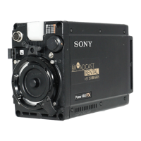
Describes maintenance information for HD MULTI PURPOSE CAMERA HDC-P1.
Lists HDC-P1 Operation Manual and Semiconductor Pin Assignments CD-ROM.
Lists trademarks and registered trademarks used in the manual.
Verifies ROM and software versions of peripheral devices before installation.
Details connector types, input/output signals, and wiring diagrams for cables.
Illustrates the physical placement of various printed circuit boards within the unit.
Provides functional descriptions for key circuit boards like PA-353P, DR-632P, TG-265PT, etc.
Step-by-step instructions for removing and installing the side panel assemblies.
Describes the purpose and normal state of LED indicators on various boards.
Details the switch settings for AT-163APT and DPR-316 boards, including factory settings.
Provides guidelines for disconnecting and connecting flexible card wires to prevent damage.
Lists EEPROM data retention and actions required after board replacement or repair.
Procedure for replacing the CCD unit, including necessary precautions and steps.
Detailed instructions for replacing specific CCD unit boards such as DR-632P and NR-80P.
Step-by-step guide for replacing the DC fan assembly, including notes on installation.
Instructions for replacing operation parts like power switch and menu switch.
Guidance on replacing connectors on front and rear panels, referring to relevant sections.
Procedure for removing and installing the rear panel assembly, including component detachment.
Details replacement procedures for various boards including CN-3283, SW-1485, and DPR-315.
Note on replacing the lithium battery on the IF-1129 board for RTC backup.
Describes the self-diagnosis function for checking communication and monitoring board status.
Information on recommended replacement parts and cleaning of air vents.
Explains the CCD block number format, showing CCD block type and serial number.
Lists optional fixtures available for extension or program upgrade.
Covers safety-related components, parts standardization, stock availability, and harnesses.
Notes regarding the use of unleaded solder, including soldering iron temperature.
Lists required measuring equipment, related equipment, and tools for electrical adjustments.
Details necessary precautions such as warm-up time, equipment calibration, and periodic maintenance.
Explains the file structure for adjustment data including Scene, Lens, Reference, and OHB files.
Recommendations for using and handling grayscale charts for electrical adjustments.
Describes how to display the SERVICE menu and change setting values using the menu control knob.
Diagram showing the connection of measuring equipment, master setup unit, and camera.
Describes initial settings for MSU-900 control panel and setup menu adjustments.
Lists camera menu items corresponding to MSU-900 adjustment items.
Procedure for executing automatic adjustment using the MSU menu or camera setup menu.
Step-by-step guide for performing BLACK SET adjustment using the SERVICE menu.
Procedure for adjusting sensitivity, including lens iris settings and waveform monitor checks.
Detailed steps for performing V-SUB adjustment for different formats.
Procedure for black shading adjustment, adjusting WFM channels to be as flat as possible.
Procedure for white shading adjustment, ensuring proper conditions and automatic white balance.
Procedure for adjusting residual point noise (RPN) using the SERVICE menu.
Details on video system level adjustments, including H/V Ratio adjustment.
Procedure for adjusting the detail level added to each step of the grayscale.
Procedure for adjusting the crispening level, setting it to reduce noise in the black-level area.
Procedure for setting Level Dep to the point where burr starts decreasing or to a user-desired level.
Procedure for adjusting the white limiter and black limiter edges to the desired clip level.
Procedure for adjusting the APL ratio and auto-iris level.
Procedure for adjusting levels A to the desired level for R, G, and B, and using Master.
Procedure for adjusting flare levels by setting level B sequentially for R, G, and B.
Procedure for adjusting gamma correction by adjusting cross points B to the desired level.
Procedure for adjusting knee point level A and knee slope level B sequentially.
Procedure for adjusting white clip level A sequentially for R, G, and B, and using Master.
Instruction to execute reference file store after completing adjustments in Section 3-4.
Procedure to correct white balance after replacing the TG-265PT board.
Details on RPN compensation, including automatic and manual procedures.
Procedure for compensating vertical line fixed-pattern noise of the CCD.
Procedure for fine adjustment of VBS outputs using waveform monitor settings.
Procedure for adjusting TEST SAW level after replacing the CCD block assembly.
Describes six types of files available for data management: Operator, Scene, Reference, Lens, OHB.
Explains storing and reading operator file data using the setup menu.
Describes calling, storing, and initializing preset operator file data.
Details storing and calling scene files using PAINT menu or MSU.
Explains storing, calling, and initializing reference files for factory settings.
Describes adjusting the lens and setting the lens file for compensating differences.
Procedure for adjusting and storing OHB file values specific to the CCD block.
Lists setting data and storage files categorized by function, with descriptions on symbols.
Describes how to display the SERVICE menu by operating the DISPLAY/MENU switch.
Lists settable special functions available by settings in the SERVICE menu.
Describes items and factory settings within the SERVICE menu, such as Scene File Type.
Information on safety-related components, standardization, stock of parts, and harnesses.
Diagrams showing exploded views of front block and related part numbers.
Lists electrical components for various boards including AT-163APT, DPR-315, DPR-316.
Illustrates the overall block diagram of the system, showing interconnected modules.
Schematic diagram for the AT-163APT board, showing component interconnections.
Schematic diagram for the CN-3282 board.
Schematic diagram for the CN-3283 board.
Schematic diagram for the DPR-315 board.
Schematic diagram for the DPR-316 board.
Schematic diagram for the DR-632P board.
Schematic diagram for the IF-1129 board.
Schematic diagram for the MB-1158 board.
Schematic diagram for the NR-80P board.
Schematic diagram for the PA-353P board.
Schematic diagram for the RE-268PT board.
Schematic diagram for the SW-1485 board.
Schematic diagram for the TG-265PT board.
Schematic diagram illustrating the frame wiring connections.
Layout diagrams for AT-163APT board (A side and B side).
Layout diagrams for CN-3282 board (A side and B side).
Layout diagrams for CN-3283 board (A side and B side).
Layout diagrams for DPR-315 board (A side and B side).
Layout diagrams for DPR-316 board (A side and B side).
Layout diagrams for DR-632P board (A side and B side).
Layout diagrams for IF-1129 board (A side and B side).
Layout diagrams for MB-1158 board (A side and B side).
Layout diagrams for NR-80P board (A side and B side).
Layout diagrams for PA-353P board (A side and B side).
Layout diagrams for RE-268PT board (A side and B side).
Layout diagrams for SW-1485 board (A side and B side).
Layout diagrams for TG-265PT board (A side and B side).
| operating temperature | -20°C to +45°C |
|---|---|
| storage temperature | -20°C to +60°C |
| signal-to-noise ratio | 55 dB |
| power requirements | 10.5 V DC to 17 V DC |
|---|---|
| power consumption | 24W |
| genlock input | 0.6 Vp-p, 75 Ω |
| pickup device | 3-chip 2/3-inch type CCD |
|---|---|
| effective picture elements | 1920 x 1080 |
| horizontal resolution | 1000 TV lines |
| weight | 1.7 kg |
|---|---|
| width | 86 mm |
| height | 212 mm |