Do you have a question about the Sony HDR-HC9 and is the answer not in the manual?
Details on recording systems, image sensor, lens, connectors, and LCD display.
Power requirements, operating conditions, physical dimensions, and battery/adapter details.
Method for supplying power during repairs to prevent auto shut-off.
Procedures for force ejecting a cassette and setting forced power on modes.
Comprehensive diagrams showing the overall system architecture and signal flow.
Diagrams illustrating the power distribution and supply circuits within the device.
Visual breakdown of the camera into major assemblies for part identification.
Comprehensive list of electrical components with part numbers and descriptions.
List of included accessories with part numbers and descriptions.
| Optical Zoom | 10x |
|---|---|
| Digital Zoom | 120x |
| Effective Pixels | 2.1 MP |
| Optical Sensor Resolution | 3.2 MP |
| Lens | Carl Zeiss Vario-Sonnar T* |
| Viewfinder | Color |
| Recording Media | MiniDV tape |
| Image Stabilization | Optical SteadyShot |
| Type | Camcorder |
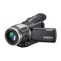
| Recording Format | HDV |
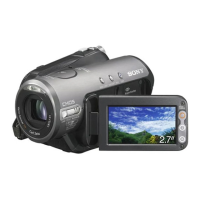
| LCD Screen | 2.7 inches |
| Interface | USB |
| Battery | NP-FH60 |