Do you have a question about the Sony HDR-HC1 and is the answer not in the manual?
Covers power supply during repairs, cassette ejection, and forced ON modes.
Instructions for using the service jig and self-diagnosis functions.
Detailed table of self-diagnosis error codes and their corrections.
Procedure for resolving flash errors after repair.
Step-by-step guide for dismantling the camcorder.
Methods for attaching specific flexible boards (FP-248, FP-259).
Overall component layout and interconnections.
List of schematic diagrams for various boards and units.
Collection of printed wiring board layouts and notes.
Illustrations of signal waveforms for testing and debugging.
Visual guides for component locations on PCBs.
Diagrams showing disassembled parts of camcorder assemblies.
List of electrical components with part numbers and references.
| Filter size | 37 mm |
|---|---|
| Digital zoom | 120 x |
| Optical zoom | 10 x |
| Focal length range | 5.1 - 51 mm |
| Total megapixels | 2.97 MP |
| Optical sensor size | 1/3 \ |
| I/O ports | Audio Out, i.LINK(DV)In/Out, S-Video Out, USB Terminal, Video Out |
| Power requirements | AC-L15 |
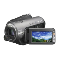
| Display diagonal | 2.7 \ |
| Display resolution | 123200 pixels |
| Camera shutter speed | 1/2-1/10000 s |
| Built-in microphone | Yes |
| Playback zoom (max) | No x |
| Minimum illumination | 7 lx |
| Battery type | NP-FM50 |
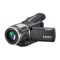
| Camcorder tape type | HDV |
| Viewfinder resolution | 252000 pixels |
| S-Video in | No |
| Depth | 188 mm |
|---|---|
| Width | 71 mm |
| Height | 94 mm |
| Weight | 680 g |