2-9 (E)
HDC-P1
2-7. Replacement of Boards
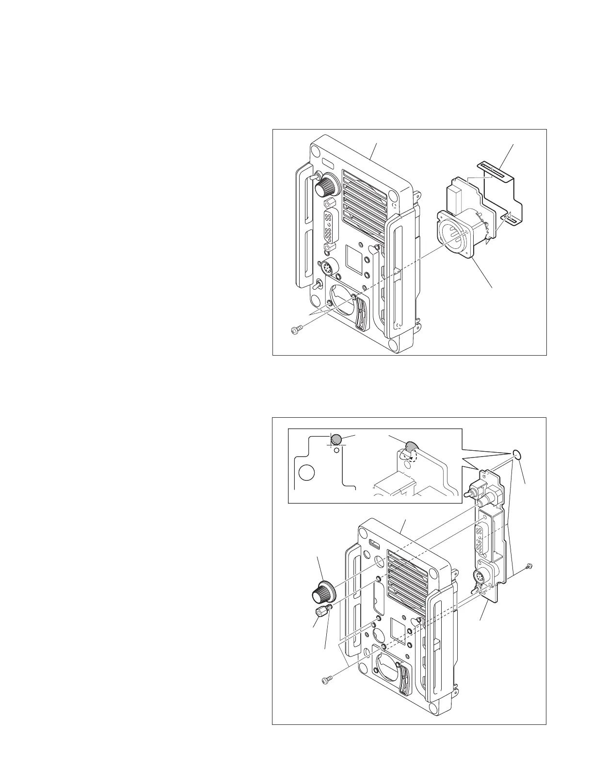
2-7-1. CN-3283 Board
1. Remove the side panel (L) assembly and the
side panel (R) assembly.
(Refer to Section 1-5.)
2. Remove the rear panel assembly.
(Refer to Section 2-6.)
3. Remove the two screws and remove the
CN-3283 board.
4. Detach the insulating sheet from the CN-3283
board.
5. Install the new CN-3283 board by reversing
the steps of removal.
2-7-2. SW-1485 Board
1. Remove the side panel (L) assembly and the
side panel (R) assembly.
(Refer to Section 1-5.)
2. Remove the rear panel assembly.
(Refer to Section 2-6.)
3. Disconnect the harness from the DC fan.
(Refer to Section 2-3 step 3.)
4. Remove the CN-3283 board.
(Refer to Section 2-7-1.)
5. Remove the fi ve screws, two connector
screws, and the encoder knob to detach the
SW-1485 board.
6. Install the new SW-1485 board by reversing
the steps of removal.
m
. When installing the SW-1485 board, attach tape
A at the location shown in the fi gure.
. Apply locking compound to the threads of the
connector screws when screwing them.
Rear panel assembly
Insulating sheet
CN-3283 board
M2.6 x 5
Rear panel assembly
Insulating sheet
CN-3283 board
M2.6 x 5
B
Rear panel assembly
Encoder knob
Connector
screws
Apply locking
compound
SW-1485 board
M2.6 x 5
PSW
M2 x 5
Tape A position
Tap e A
Tap e A
Fold back
tape A
B
Rear panel assembly
Encoder knob
Connector
screws
Apply locking
compound
SW-1485 board
M2.6 x 5
PSW
M2 x 5
Tape A position
Tap e A
Tap e A
Fold back
tape A
 Loading...