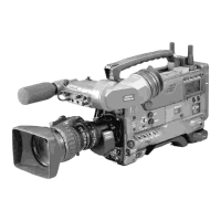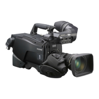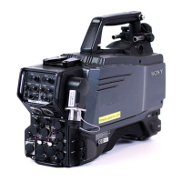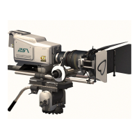
Do you have a question about the Sony HDCAM HDW-F900R and is the answer not in the manual?
| Recording Format | HDCAM |
|---|---|
| Resolution | 1920 x 1080 |
| Frame Rates | 23.98p, 24p, 25p, 29.97p, 50i, 59.94i |
| Audio Channels | 4 |
| Signal-to-Noise Ratio | 54 dB |
| Recording Media | HDCAM tape |
| Sensitivity | F11 at 2000 lux |
| Shutter Speed | 1/2000 sec |
| Recording Time | Approx. 40 minutes (with HDCAM tape) |
| Sensor Type | 3x 2/3-inch CCD |
Explains the purpose and scope of this maintenance manual volume 1.
Lists other available manuals relevant to the unit.
Details circuit configuration and locations of the printed wiring boards.
Lists connectors at the ends of cables for installation and maintenance.
Describes signal inputs and outputs for the camcorder.
Provides procedures for removing and reinstalling the outside panel.
Details the procedure for opening and closing the inside panel.
Outlines steps for removing and reinstalling the connector box.
Explains how to remove and reinstall plug-in boards.
Details the procedure for removing and reinstalling flexible card wires.
Provides instructions for removing and reinstalling the cassette compartment.
Describes the functions of on-board switches and slit lands.
Step-by-step guide to manually ejecting a cassette tape.
Procedure for cleaning clogged video heads using a cleaning tape.
Lists essential tools and measuring equipment for maintenance.
Instructions on how to extend circuit boards using extension assemblies.
Lists adjustments and settings required after board replacement.
Details the data stored in EEPROM, NV-RAM, and FRAM on various boards.
Explains when error codes appear, indicating unit abnormalities.
Lists and describes various error codes with their causes.
Provides detailed information on error codes, detecting conditions, and suspected causes.
Lists the available setup menus for settings and adjustments.
Describes the TOP menu and its functions.
Details the USER menu for selecting and storing frequently used functions.
Explains the OPERATION menu for setting preferences and shooting conditions.
Describes the PAINT menu for fine adjustment of pictures via waveform monitor.
Covers the camera maintenance menu for settings affecting operating frequency.
Outlines the file operation menu for saving data in REFERENCE files.
Details the DIAGNOSIS menu for checking VTR status and diagnosing errors.
Explains the SERVICE menu for service and maintenance operations.
Provides a comprehensive list of all setup menu items and their default settings.
Explains the file system structure, including USER, ALL, SCENE, REFERENCE, and LENS files.
Instructions on calling, modifying, and registering USER files.
Details on calling, modifying, and registering ALL files.
Procedures for saving and calling SCENE files.
Instructions for saving and loading REFERENCE files.
Covers special saving items, focusing on White Gain, Master Gain, and Shutter.
Details the procedure for replacing the CCD unit and its components.
Procedure for replacing shutter, AUTO W/B BAL switch, and audio volume controls.
Procedure for replacing the DC-DC converter.
Steps for replacing the VF connector.
Instructions for replacing the CCM-45G board.
Instructions for replacing the SS-92G board.
Details the replacement of mechanical deck assembly boards.
Provides general information and notes on mechanical part replacement.
Step-by-step procedure for replacing the upper drum assembly.
Instructions for replacing the drum assembly.
Procedure for replacing the brush assembly for the slip ring.
Instructions for replacing the slip ring assembly.
Procedure for replacing the AHC roller assembly for the video head.
Steps for replacing the pinch roller assembly.
Instructions for replacing the S-tension regulator band assembly.
Procedure for replacing the T-tension regulator band assembly.
Instructions for replacing the timing belt.
Procedure for replacing S and T idler assemblies.
Steps for replacing the CTL head.
Instructions for replacing the FE head.
Procedure for replacing the holder assembly sensor (REC).
Instructions for replacing the end sensor assembly.
Steps for replacing the full top sensor assembly.
Procedure for replacing S1, T1, and T3 tape guides.
Instructions for replacing the (S) soft brake assembly.
Procedure for replacing the T soft brake.
Steps for replacing the manual eject assembly.
Instructions for replacing the S-tension regulator assembly.
Procedure for replacing the T-tension regulator assembly.
Steps for replacing the cassette stopper.
Procedure for replacing the gear block assembly.
Instructions for replacing S and T reel table assemblies.
Procedure for replacing the reel drive gear assembly.
Steps for replacing the holder assembly sensor (ID).
Instructions for replacing the top sensor assembly.
Procedure for replacing the pinch arm assembly.
Instructions for replacing the threading arm assembly.
Steps for replacing the CUE/TC head assembly.
Instructions for replacing the S slider assembly.
Procedure for replacing the T slider assembly.
Steps for replacing the cam gear assembly.
Instructions for removing and installing the mechanical deck assembly.
Procedure for replacing the MDC-13G board.
Instructions for replacing the capstan motor.
Covers automatic adjustment of the mechanism.
Procedure for adjusting the reel table height.
Instructions for adjusting the S tension regulator operating position.
Procedure for adjusting the FWD back tension.
Instructions for adjusting the REV back tension.
Procedure for adjusting the timing belt tension.
Instructions for adjusting the T tension regulator operating position.
Procedure for adjusting the S3 guide height.
Instructions for adjusting the gear chain phase.
Covers tape run system adjustments.
Procedure for adjusting the tape run.
Instructions for adjusting video tracking.
Procedure for adjusting the CTL head height.
Instructions for adjusting the CTL head position.
Procedure for adjusting the CUE/TC head height.
Instructions for adjusting the CUE/TC head azimuth.
Procedure for adjusting CUE/TC head tape-to-head contact.
Instructions for adjusting the CUE/TC head position.
Provides general information on electrical alignment procedures.
Details the initial switch positions required for adjustments.
Information on using and maintaining gray-scale charts for adjustments.
Procedure for adjusting the VCO frequency.
Instructions for adjusting the TEST OUT level.
Procedure for adjusting the VF DC level.
Instructions for adjusting the VA gain.
Procedure for adjusting the black offset.
Instructions for adjusting black shading.
Procedure for adjusting white shading.
Procedure for adjusting gamma correction.
Instructions for adjusting knee and white clip.
Instructions for adjusting crispening.
Procedure for adjusting level depend.
Instructions for adjusting detail signal frequency.
Procedure for adjusting H/V ratio.
Instructions for adjusting detail signal level.
Procedure for adjusting knee aperture.
Instructions for adjusting H. detail black clip.
Procedure for adjusting V. detail black clip.
Instructions for adjusting skin tone.
Procedure for adjusting zebra settings.
Instructions for adjusting auto iris.
White balance correction procedure after filter disc unit replacement.
Procedure for adjusting SD VCO.
Instructions for adjusting SD Y level.
Procedure for adjusting SD ZEBRA clamp level.
Instructions for adjusting SD ZEBRA Y level.
Procedure for adjusting VF 2-3 pull down HD Y level.
Details RPN concealment procedures.
Lists required equipment, fixtures, and tools for VTR electrical alignment.
Procedure for aligning the audio system.
Steps for CUE audio alignment, including bias trap and playback level.
Details the servo system adjustment procedures.
Overview of the VTR maintenance mode and its menu structure.
Explains how to operate the VTR maintenance mode.
Identifies the switches used for VTR maintenance mode operation.
Step-by-step guide to entering the VTR maintenance mode.
Lists the contents of the menus within the VTR maintenance mode.
Details the Servo System Self-Diagnosis Mode for checking sensors.
Explains the RF System Self-Diagnosis Mode for checking error conditions.
Mode for checking audio system adjustment values.
Mode for automatically adjusting the servo system.
Mode for automatically adjusting the RF system.
Mode for adjusting the audio system.
Mode for setting items required for mechanism adjustment.
Adjustments for internal circuit voltage correction and board replacement.