Do you have a question about the Sony HDR-CX220 and is the answer not in the manual?
Details the version updates and release dates of the service manual.
Essential safety checks to perform after service to ensure safe operation.
Guidelines for handling and using unleaded solder and identifying lead-free components.
Detailed list of electronic components, their part numbers, and descriptions.
High-level system architecture illustrating interconnected major components.
Second part of the overall system block diagram detailing component connections.
Third part of the overall system block diagram illustrating component interconnections.
Diagram showing the power supply distribution and management within the system.
Second part of the power block diagram illustrating power supply pathways.
Third part of the power block diagram detailing power supply distribution.
Top-level connection diagram showing major board interconnections.
Second part of the frame schematic diagram showing board connections.
General conventions and notations used in schematic diagrams.
Conventions and notations for printed wiring board diagrams.
Guidelines and warnings for replacing critical components and imagers.
Physical layout of components on the CM-1004 board, both sides.
| Sensor type | CMOS |
|---|---|
| Total megapixels | 8.9 MP |
| Optical sensor size | 1/5.8 \ |
| Digital zoom | 320 x |
| Optical zoom | 27 x |
| Image stabilizer | Yes |
| Focal length range | 2.1 - 57 mm |
| Interchangeable lens | - |
| Maximum aperture number | 4 |
| Minimum aperture number | 1.9 |
| Focal length (35mm film equivalent) | 29.8 - 953.6 mm |
| Camcorder media type | Memory card |
| Disc types supported | No |
| Compatible memory cards | MS PRO Duo, MS Pro-HG Duo, SD, SDHC, SDXC |
| Internal storage capacity | - GB |
| Camera shutter speed | 1/8 - 1/10000 s |
| Display diagonal | 2.7 \ |
| Display aspect ratio | 16:9 |
| Display resolution (numeric) | 230000 pixels |
| Viewfinder type | Not available |
| Camcorder type | Handheld camcorder |
| Shooting modes | Manual, Movie |
| Camera playback | Movie, Single image |
| Minimum illumination | 3 lx |
| Product color | Blue |
| Video resolutions | 1440 x 1080, 1920 x 1080 pixels |
| Video formats supported | AVCHD, H.264, MPEG2, MPEG4 |
| Maximum video resolution | 1920 x 1080 pixels |
| Image formats supported | JPG |
| Maximum image resolution | 3984 x 2240 pixels |
| Still image resolution(s) | 2992 x 2240, 3984 x 2240 |
| Audio system | Dolby Digital 2.0 |
| USB 2.0 ports quantity | 1 |
| Battery type | NP-FV30 |
| Battery capacity | - mAh |
| Battery life (max) | - h |
| Depth | 117 mm |
|---|---|
| Width | 52.5 mm |
| Height | 57 mm |
| Weight | 178 g |

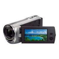
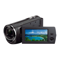
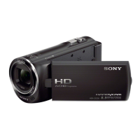
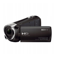
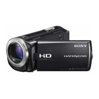


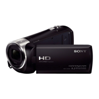
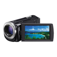
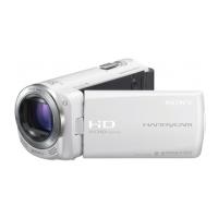
 Loading...