Do you have a question about the Sony HDR-XR500 and is the answer not in the manual?
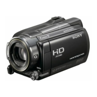
Details about video, audio, photo formats, recording media, viewfinder, image device, and lens.
Lists available audio, video, USB, headphone, and microphone connectors.
Covers power requirements, consumption, operating conditions, dimensions, and mass.
Details power requirements, consumption, voltage, and operating conditions for AC adaptor.
Details voltage, capacity, and type of the rechargeable battery pack.
Critical components for safe operation and replacement guidelines.
Post-repair checks to ensure safe operation before releasing to customer.
Method to prevent power shut-off during repair operations.
Guidelines for replacing the VC-557 board, including data handling.
Connection details for service jigs used in repairs and adjustments.
Explains the unit's self-diagnosis function and display modes.
Describes the 4-digit display format indicating repairer, block, and detailed error code.
Lists diagnostic codes, symptoms, and correction procedures for troubleshooting.
Troubleshooting steps for IC abnormality in the steadyshot function.
Procedure to diagnose and resolve shift lens overheating in the pitch direction.
Procedure to diagnose and resolve shift lens overheating in the yaw direction.
Troubleshooting steps for thermistor abnormalities in the lens system.
Important checks for flexible cables, connectors, and wire handling during disassembly.
Safety procedure to discharge the ST-206 board's capacitor before handling.
Instructions for creating a short jig for capacitor discharge.
Identifies key components and their locations within the camera assembly.
Provides a structured sequence for disassembling major sections of the camera.
Step-by-step instructions for disassembling the Hard Disk Drive module.
Detailed steps for disassembling the camera's overall structure, including cabinets and switch blocks.
Instructions for disassembling the top cabinet, EVF, and hot shoe components.
Steps for disassembling the front cabinet, BT panel, and related parts.
Procedures for disassembling the lens block and associated boards.
Steps for disassembling the main internal boards like ST, VC-557, and MD-143.
Instructions for disassembling the right cabinet, control switches, CK-211 board, and LCD section.
Steps for disassembling the LCD screen assembly, including hinge and PD-381 board.
A collection of diagrams illustrating the camera's overall functional blocks.
Diagrams detailing the power distribution and management within the camera.
Schematic showing the interaction between CM-103, VC-557, and CPU for signal processing.
Schematic illustrating connections between VC-557, CPU, and various interface boards.
Schematic detailing connections related to the FR-298 board, CPU, and optical image stabilizer components.
Schematic showing the control switch block, VC-557 board, and lens system interconnections.
Schematic illustrating connections between MD-143, VC-557, and flexible boards for various functions.
Schematic showing connections between MS-414, EG-001, HDMI processor, and flexible boards.
Schematic detailing connections for LANC interface, microphone unit, hot shoe, and flexible boards.
Schematic showing connections for CK-211, PD-381, GPS Assy, and touch panel interface.
Diagram illustrating power supply lines from battery, AC adapter, and regulators.
Schematic showing power distribution to various boards like MD-143, EG-001, and HDMI transmitter.
Diagram detailing power distribution to boards like ST-206, VC-557, and MS-414.
Schematic for the CK-211 board, related to control switches.
Schematic for the EG-001 board, covering peripheral connections.
Schematic for the MA-456 board, including microphone and hot shoe connections.
Schematic for the MS-414 board, detailing memory stick connections.
Schematic for the ST-206 board, including flash drive and capacitor circuits.
Schematic for the BL-031 board, related to the EVF and backlight.
Schematic for the FP-1034 flexible board connecting VC and MD boards.
Schematic for the FP-1036 flexible board connecting VC and CM boards.
Schematic for the FP-1038 flexible board connecting VC and HDD.
Schematic for the FP-1040 flexible board connecting VC and ST boards.
Schematic for the FP-1043 flexible board connecting MD and CK boards.
Schematic for the FP-1046 flexible board handling HDMI and USB connections.
Schematic for the FP-1049 flexible board for the hot shoe connection.
Schematic for the control switch block functions.
Schematic for the power switch block.
Schematic for the PD-381 board.
Schematic for the GPS assembly.
Information on test patterns and connections for waveform measurement.
Details on voltage and waveform measurement standards for reference.
Guidelines for handling and replacing the imager component to prevent damage.
Printed wiring layout for the CK-211 control switch board.
Printed wiring layout for the EG-001 board.
Printed wiring layout for the MS-414 board.
Printed wiring layout for the ST-206 board.
Printed wiring layout for the FP-1034 flexible board.
Printed wiring layout for the FP-1036 flexible board.
Printed wiring layout for the FP-1038 flexible board.
Printed wiring layout for the FP-1040 flexible board.
Printed wiring layout for the FP-1043 flexible board.
Printed wiring layout for the FP-1046 flexible board.
Printed wiring layout for the FP-1049 flexible board.
List of electrical components for the ST-206 board.
List of electrical components for the BL-031 board.
List of electrical components for the FP-1034 flexible board.
List of electrical components for the FP-1035 flexible board.
List of electrical components for the FP-1044 flexible board.
List of electrical components for the FP-1045 flexible board.
List of electrical components for the FP-1046 flexible board.
List of electrical components for the FP-1047 flexible board.
List of electrical components for the FP-1048 flexible board.
List of electrical components for the FP-1049 flexible board.
Visual guides showing the breakdown of camera components for repair.
Exploded view of the Hard Disk Drive module and its related parts.
Exploded view of the main camera body and overall assembly.
Exploded view of the lens assembly and its components.
Exploded view of the main internal boards and their placement.
Exploded view of the LCD screen assembly and related parts.
Exploded view of the Electronic Viewfinder assembly.
List of electrical components for the BL-031 board.
List of electrical components for the CK-211 board.
Lists electrical components for various flexible boards.
List of electrical components for the MA-456 board.
List of electrical components for the MS-414 board.
List of electrical components for the ST-206 board.
Details of the included AC power adapter.
Information on the included wireless remote control.
Details of the included rechargeable battery pack.
Information about the included CD-ROM containing application software and manuals.
Manuals providing instructions for operating the camcorder and its features.
Visual guides showing the breakdown of camera components for repair.
Exploded view of the Hard Disk Drive module and its related parts.
Exploded view of the main camera body and overall assembly.
Exploded view of the lens assembly and its components.
Exploded view of the main internal boards and their placement.
Exploded view of the LCD screen assembly and related parts.
Exploded view of the Electronic Viewfinder assembly.
| Sensor Type | CMOS |
|---|---|
| Sensor Size | 1/2.88 inch |
| Lens | Carl Zeiss Vario-Sonnar T* |
| Optical Zoom | 12x |
| Digital Zoom | 150x |
| Image Stabilization | Optical SteadyShot |
| Recording Media | HDD, Memory Stick PRO Duo |
| HDD Capacity | 120GB |
| Display | LCD |
| LCD Screen Resolution | 921, 000 dots |
| Video Resolution | 1920 x 1080 |
| Video Format | AVCHD |
| Effective Pixels | 6.6 megapixels |
| Maximum Aperture | f/1.8-3.4 |
| LCD Screen Size | 3.2 inches |