7
Locations and Functions of Parts
Locations and Functions of Parts
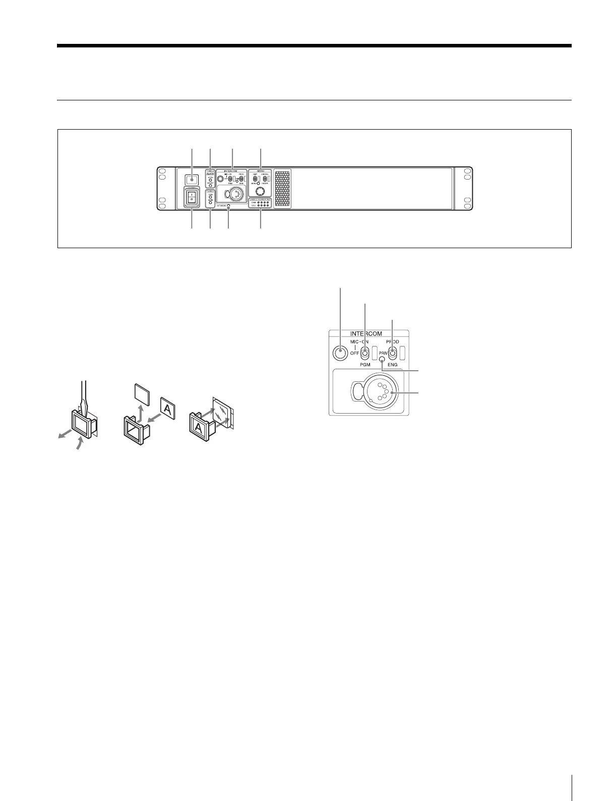
Front Panel
a Tally light
Turns on red to indicate a red tally signal is being received
(such as when the picture from the camera connected to the
CCU is being used). When the CALL button on the camera,
the MSU-1000/1500 Master Setup Unit, or the RCP-1000-
series Remote Control Panel is pressed, the light turns off if lit
or turns on if not lit.
Turns on green to indicate a green tally signal is being
received.
A number plate supplied with the CCU can be attached (see
the following figure).
b CABLE ALARM indicators
OPEN: Turns on when a camera is not connected (open
circuit) to the CAMERA connector on the rear panel via an
optical fiber cable or a triax cable. While on, the CCU does
not supply any power to the camera.
It flashes if there is a transmission error between the
camera and CCU.
SHORT: Turns on when there is an overcurrent condition
(short circuit) on the optical fiber cable or triax cable. While
on, the CCU does not supply any power to the camera.
c INTERCOM audio input/output and control block
• INTERCOM (intercom adjustment) knob
Adjusts the headset audio level.
• MIC/PGM (microphone/program) switch
ON: Turns the headset microphone on.
OFF: Turns the headset microphone off.
PGM: Selects program audio output.
• INTERCOM (intercom select) switch
Selects the intercom signal input/output connection source for
the INTERCOM connector on the rear panel.
PROD: Connects the producer line.
PRIV: Disconnects both the producer line and engineer line,
allowing private communication between CCU and camera
only.
ENG: Connects the engineer line.
• PRIV indicator
Turns on when the intercom is in private mode.
• INTERCOM connector (XLR 5-pin)
Intercom headset connection.
a
ef hg
bc d
INTERCOM (intercom adjustment) knob
MIC/PGM (microphone/program) switch
INTERCOM (intercom select) switch
INTERCOM connector
PRIV indicator