8
Locations and Functions of Parts
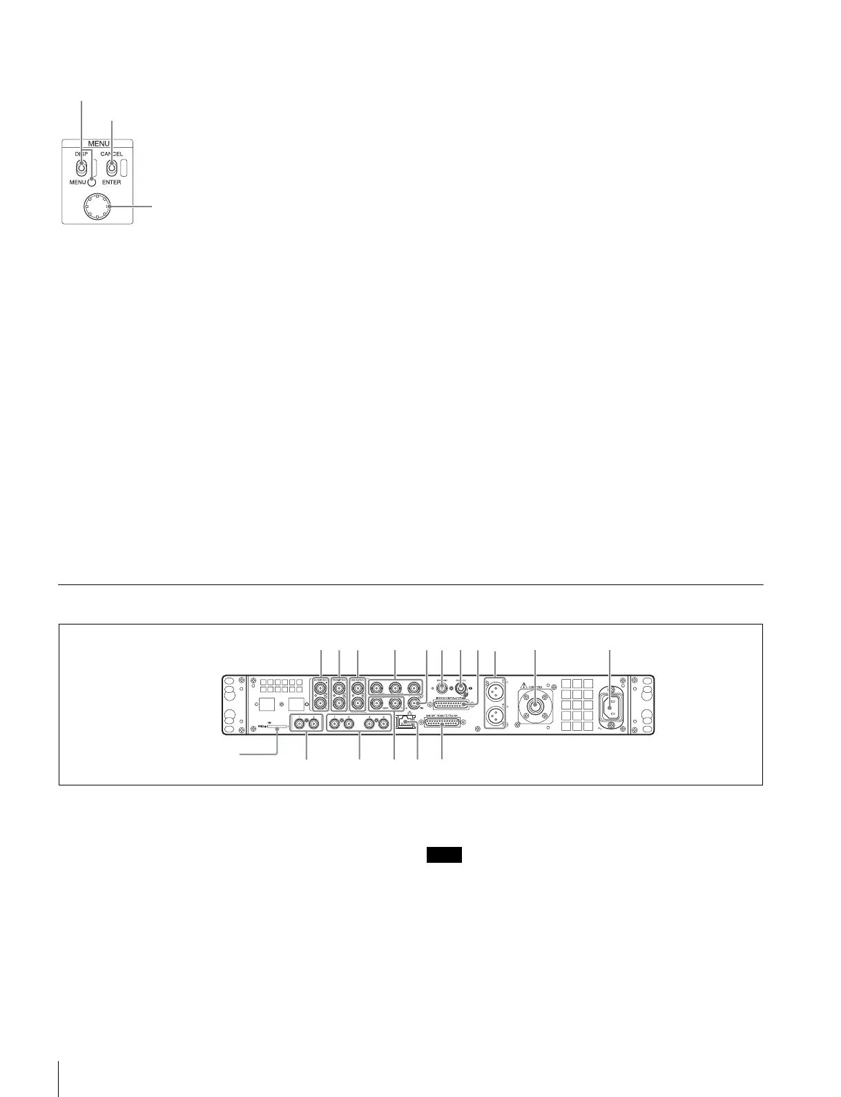
d MENU control block
• DISP/MENU (display/menu) lever and indicator
Selects the status display or setup menu display. In setup
menu mode, the indicator turns on.
• CANCEL/ENTER lever
In setup menu mode, used to cancel and enter settings.
• Control knob (rotary encoder)
In status screen mode, used to change the displayed page. In
setup menu mode, used to move the cursor on a page and to
change menu settings.
Pressing the control knob performs the same function as
setting the CANCEL/ENTER lever to the ENTER position.
e POWER switch
Switches the power for the entire system on and off, including
the CCU, camera, and the RCP-1000-series Remote Control
Panel connected to the REMOTE connector on the rear panel.
Pressing the “?” side turns the camera system on, and
pressing the “a” side turns it off.
f POWER indicator
CAM: Turns on when power is supplied to the camera.
MAIN: Turns on when the CCU power supply is turned on. It
flashes when there is a problem with the fan.
g NETWORK indicator
Displays the network system connection status.
On: Indicates that external control equipment
(MSU-1000/1500 Master Setup Unit, RCP-1000-series
Remote Control Panel, or other device) is connected.
Flashing: Indicates a connection problem with the external
control equipment (MSU-1000/1500 Master Setup Unit,
RCP-1000-series Remote Control Panel, or other device).
Off: Indicates that a LAN cable is not connected or that the
network system connection parameters have not been set.
See “Network diagnostics” on page 14 and “NETWORK
SETTINGS menu” on page 28.
h CABLE CONDITION indicators
Indicates the communication status of the camera (CAM) and
camera control unit (CCU).
When the two lamps on the right (green) are lighted:
Reception status is excellent.
When the second lamp from the right (green) is lighted:
Reception status is good.
When the second lamp from the left (yellow) is lighted:
Reception status is low.
When the lamp on the left (red) is lighted: Reception status
is at the lowest level.
• On the HSCU300RF, determined by the receive level of the
optical signal on the camera and CCU.
• On the HSCU300R, determined by the receive level of the
RF signal on the CCU.
Rear Panel
a REFERENCE IN/OUT (reference input) connectors
(BNC type)
Inputs an HD tri-level reference sync signal or SD reference
sync signal (black burst signal) on either of the two connectors.
The input signal is output from the other connector as-is (loop-
through output). The signal is input on the upper connector.
The lower connector is terminated automatically if no
connector is connected.
b PROMPTER 1, 2 (teleprompter input 1, 2) connectors
(BNC type)
Inputs the VBS signals for the teleprompter.
On the HSCU300RF, only one system from the two systems on the
PROMPTER1 and 2 connectors is enabled.
c VBS RETURN 1, 2 (VBS return video 1, 2 input)
connectors (BNC type)
Inputs the 2-system VBS return video signals.
DISP/MENU (display/menu) lever and indicator
CANCEL/ENTER lever
Control knob
abc
lomn p
dgfheij k
Memory stick slot (for use
by service personnel only)
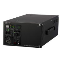
HSCU300RF diagram shown.
Note
 Loading...