6-32
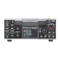
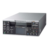
HVR-M25J/M25U/M25N/M25E/M25P/M25C
2-1-3. Connecting the Equipment
Connect the measuring instruments as shown in Fig. 6-2-1, and
perform the adjustments.
Fig. 6-2-1
Pin No. Signal Name Pin No. Signal Name
1 EVF_COM_DC (N.C.) 2 REG_GND
3 REG_GND 4 MT_5.5V
5 EXT_DA (N.C.) 6 REG_GND
7 EVF_VCO (N.C.) 8 MS_LED_ON
9 EVF_VG (N.C.) 10 MS_BS
11 PSIG (N.C.) 12 MS_SCLK
13 RF_MON 14 MS_VCC_ON
15 SWP 16 XMS_IN
17 FRRV 18 MS_DIO
19 REC_CRRT1 (N.C.) 20 REC_CRRT0 (N.C.)
6-2. VIDEO SECTION ADJUSTMENTS
2-1. PREPARATIONS BEFORE ADJUSTMENTS
Use the following measuring instruments for video section adjust-
ments.
2-1-1. Precautions on Adjusting
Note: Before performing the adjustment, check the data of page:
0, address: 10 is “00”. If not, select page: 0, address: 00,
and set data “00”.
2-1-2. Adjusting Connectors
The measuring point of the playback RF signal is CN4002 of VD-
036 board. Connect the measuring instruments via the CPC-8 jig
(J-6082-388-A). Refer to “MECHANISM SECTION ADJUST-
MENT” for the measuring method. The following table lists the
pin numbers and signal names of CN4002.
Pattern generator
VIDEO OUT
Osilloscope
Terminated
75 Ω
LANC jack
Adjustment remote commander
RM-95
(J-6082-053-B)
NEW LANC JIG
(J-6082-565-A)
LANC cable
(J-6082-442-A)
75Ω : 1-247-804-11
Table. 6-2-1
 Loading...