EasyManua.ls Logo

Sony HCD-EP30 User Manual

Sony HCD-EP30
38 pages
To Next Page IconTo Next Page
Page #1 background imageLoading...
Page #1 background image
SERVICE MANUAL
COMPACT DISC DECK RECEIVER
US Model
Canadian Model
E Model
Australian Model
HCD-EP30
AEP Model
UK Model
HCD-EP30/EP40
SPECIFICATIONS
HCD-EP30/EP40
Photo: HCD-EP40
Ver 1.0 2001.04
HCD-EP30/EP40 are the amplifier, CD
player, tape deck and tuner section in
CMT-EP30/EP40.
CD Section CD Mechanism Type CS-21SC-1280
TAPE Section Tape Transport Mechanism Type TCM125-2
9-873-867-11 Sony Corporation
2001D0500-1 Home Audio Company
C 2001.4 Shinagawa Tec Service Manual Production Group
Amplifier section
AUDIO POWER SPECIFICATIONS:
(US model only)
POWER OUTPUT AND TOTAL
HARMONIC DISTORTION:
with 4 loads both channels driven, from 120
- 10,000 Hz; rates 5 W per channel minimum
RMS power, with no more than 10% total
harmonic distortion from 250 mW to rated
output.
Canadian model:
Continuous RMS power output (reference)
5 + 5 W
(4 at 1 kHz, 10% THD)
AEP, UK models:
DIN power output (rated) 4.5 + 4.5 W
(4 at 1 kHz, DIN)
Continuous RMS power output (reference)
5 + 5 W
(4 at 1 kHz, 10% THD)
Music power output (reference)
13 + 13 W
Other models:
The following measured at AC 230 V, 50/60 Hz
DIN power output (rated) 4.5 + 4.5 W
(4 at 1 kHz, DIN)
Continuous RMS power output (reference)
5 + 5 W
(4 at 1 kHz, 10% THD)
Outputs
PHONES: Accepts headphones of
(stereo mini jack) 8 or more
SPEAKER: Accepts impedance of 4 to
16
CD player section
System Compact disc and digital
audio system
Laser Semiconductor laser
(λ=780 nm)
Emission duration:
continuous
Frequency response 20 Hz - 20 kHz (±0.5 dB)
Tape player section
Recording system 4-track 2-channel stereo
Frequency response 50 - 13 000 Hz (±3 dB),
using Sony TYPE I
cassette
Tuner section
FM stereo, FM/AM superheterodyne tuner
FM tuner section
Tuning range 87.5 - 108.0 MHz
Antenna FM lead antenna
Intermediate frequency 10.7 MHz
AM tuner section
Tuning range
Pan-American model: 530 - 1 710 kHz
(with the interval set at
10 kHz)
531 - 1 602 kHz
(with the interval set at
9 kHz)
European model:
531 -1 602 kHz
(with the interval set at
9 kHz)
Other models: 531 - 1 602 kHz
(with the interval set at
9 kHz)
530 - 1 710 kHz
(with the interval set at
10 kHz)
Antenna Built-in ferrite bar antenna
Intermediate frequency 450 kHz
General
Power requirements
US, Canadian models: 120 V AC, 60 Hz
AEP, UK models: 230 V AC, 50/60 Hz
Australian model: 230 V AC, 50/60 Hz
Mexican model: 120 V AC, 60 Hz
Argentine model: 220 V AC, 50/60 Hz
Taiwan model: 110 V AC, 60 Hz
Other models: 230 V AC, 50/60 Hz
Power consumption
US model: 25 W
Canadian model: 25 W
AEP, UK models: 30 W
0.9 W (in the standby
mode)
Other models: 30 W
Dimensions (w/h/d):
Approx. 145 × 238 × 238 mm
Mass: Approx. 2.8 kg
Design and specifications are subject to change
without notice.
w
w
w
.
x
i
a
o
y
u
1
6
3
.
c
o
m
Q
Q
3
7
6
3
1
5
1
5
0
9
9
2
8
9
4
2
9
8
T
E
L
1
3
9
4
2
2
9
6
5
1
3
9
9
2
8
9
4
2
9
8
0
5
1
5
1
3
6
7
3
Q
Q
TEL 13942296513 QQ 376315150 892498299
http://www.xiaoyu163.com
Question and Answer IconNeed help?

Do you have a question about the Sony HCD-EP30 and is the answer not in the manual?

Sony HCD-EP30 Specifications

General IconGeneral
Tuner BandsFM, MW
Cassette DeckDual Cassette Deck
Playback FormatCD, Cassette
Power Output20 W
TypeMini Hi-Fi System

Summary

HCD-EP30/EP40 Service Manual Overview

Model Identification

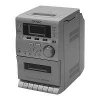
Identifies product models and lists key technical specifications.

Technical Specifications

Lists key technical specifications for the HCD-EP30/EP40 unit.

Safety and Testing Procedures

Safety Check-out Steps

Outlines essential safety checks to perform after repairs.

AC Leakage Test Procedure

Details the method for testing AC leakage current from exposed metal parts.

Critical Component Safety Warning

Highlights components critical for safety and replacement instructions.

SECTION 1 SERVICING NOTES

Handling the Optical Pick-up Block

Notes on handling optical components, laser diode emission, and focus search.

Laser Diode Emission Check

Notes on checking laser diode emission from the optical pick-up block.

Laser Diode and Focus Search Operation Check

Procedure for checking laser diode and focus search operation.

Preventing Tape Oscillation Sound

Method to prevent tape oscillation sound at maximum volume.

SECTION 2 GENERAL

Front Panel Controls and Buttons

Identifies controls and buttons on the front panel.

Button Descriptions

Detailed descriptions of each button on the unit.

Remote Control Operation

Remote Control Overview

Overview of the remote control unit.

Setting the System Time

Instructions for setting the system's clock time.

SECTION 3 DISASSEMBLY

Disassembly Flow Diagram

Flowchart illustrating the disassembly sequence.

Front Panel Section Disassembly

Steps for disassembling the front panel section.

Main Board Disassembly

Steps for removing and accessing the main board.

CD Mechanism Deck Disassembly

Steps for disassembling the CD mechanism deck.

Tape Mechanism Deck Disassembly

Steps for disassembling the tape mechanism deck.

Cassette Lid Disassembly

Procedure for removing the cassette lid.

SECTION 4 MECHANICAL ADJUSTMENTS

General Precautions for Mechanical Adjustments

Precautions for performing mechanical adjustments.

Torque Measurement Procedures

Procedure for measuring torque of mechanical parts.

Tape Tension Measurement Procedures

Procedure for measuring tape tension.

SECTION 5 ELECTRICAL ADJUSTMENTS

General Precautions for Electrical Adjustments

Precautions for performing electrical adjustments.

Tape Speed Adjustment Procedure

Procedure for adjusting tape speed.

Head Azimuth Adjustment Procedure

Procedure for adjusting the head azimuth.

SECTION 6 DIAGRAMS

Notes on Printed Wiring Boards and Schematics

Guidelines for interpreting circuit diagrams and PWB patterns.

Circuit Boards Location Overview

Diagram showing the physical location of circuit boards.

SECTION 7 EXPLODED VIEWS

Cabinet Section Exploded View

Exploded view of the main cabinet and CD section.

Front Panel Exploded Views

Exploded views of the front panel components.

CD Cabinet Section Exploded View

Exploded view of the CD cabinet and related parts.

SECTION 8 ELECTRICAL PARTS LIST

Cassette Section Parts List

List of electrical parts for the cassette section.

Display Section Parts List

List of electrical parts for the display section.

Main Section Parts List

List of electrical parts for the main board.

Power Section Parts List

List of electrical parts for the power board.

REVISION HISTORY

Version 1.0 Details

Information about the revisions made to this service manual.

Related product manuals