SERVICE MANUAL
COMPACT DISC DECK RECEIVER
US Model
Canadian Model
E Model
Australian Model
HCD-EP30
AEP Model
UK Model
HCD-EP30/EP40
SPECIFICATIONS
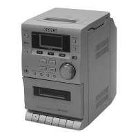
HCD-EP30/EP40
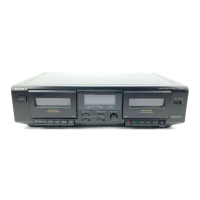
Photo: HCD-EP40
Ver 1.0 2001.04
HCD-EP30/EP40 are the amplifier, CD
player, tape deck and tuner section in
CMT-EP30/EP40.
CD Section CD Mechanism Type CS-21SC-1280
TAPE Section Tape Transport Mechanism Type TCM125-2
9-873-867-11 Sony Corporation
2001D0500-1 Home Audio Company
C 2001.4 Shinagawa Tec Service Manual Production Group
Amplifier section
AUDIO POWER SPECIFICATIONS:
(US model only)
POWER OUTPUT AND TOTAL
HARMONIC DISTORTION:
with 4 Ω loads both channels driven, from 120
- 10,000 Hz; rates 5 W per channel minimum
RMS power, with no more than 10% total
harmonic distortion from 250 mW to rated
output.
Canadian model:
Continuous RMS power output (reference)
5 + 5 W
(4 Ω at 1 kHz, 10% THD)
AEP, UK models:
DIN power output (rated) 4.5 + 4.5 W
(4 Ω at 1 kHz, DIN)
Continuous RMS power output (reference)
5 + 5 W
(4 Ω at 1 kHz, 10% THD)
Music power output (reference)
13 + 13 W
Other models:
The following measured at AC 230 V, 50/60 Hz
DIN power output (rated) 4.5 + 4.5 W
(4 Ω at 1 kHz, DIN)
Continuous RMS power output (reference)
5 + 5 W
(4 Ω at 1 kHz, 10% THD)
Outputs
PHONES: Accepts headphones of
(stereo mini jack) 8 Ω or more
SPEAKER: Accepts impedance of 4 to
16 Ω
CD player section
System Compact disc and digital
audio system
Laser Semiconductor laser
(λ=780 nm)
Emission duration:
continuous
Frequency response 20 Hz - 20 kHz (±0.5 dB)
Tape player section
Recording system 4-track 2-channel stereo
Frequency response 50 - 13 000 Hz (±3 dB),
using Sony TYPE I
cassette
Tuner section
FM stereo, FM/AM superheterodyne tuner
FM tuner section
Tuning range 87.5 - 108.0 MHz
Antenna FM lead antenna
Intermediate frequency 10.7 MHz
AM tuner section
Tuning range
Pan-American model: 530 - 1 710 kHz
(with the interval set at
10 kHz)
531 - 1 602 kHz
(with the interval set at
9 kHz)
European model:
531 -1 602 kHz
(with the interval set at
9 kHz)
Other models: 531 - 1 602 kHz
(with the interval set at
9 kHz)
530 - 1 710 kHz
(with the interval set at
10 kHz)
Antenna Built-in ferrite bar antenna
Intermediate frequency 450 kHz
General
Power requirements
US, Canadian models: 120 V AC, 60 Hz
AEP, UK models: 230 V AC, 50/60 Hz
Australian model: 230 V AC, 50/60 Hz
Mexican model: 120 V AC, 60 Hz
Argentine model: 220 V AC, 50/60 Hz
Taiwan model: 110 V AC, 60 Hz
Other models: 230 V AC, 50/60 Hz
Power consumption
US model: 25 W
Canadian model: 25 W
AEP, UK models: 30 W
0.9 W (in the standby
mode)
Other models: 30 W
Dimensions (w/h/d):
Approx. 145 × 238 × 238 mm
Mass: Approx. 2.8 kg
Design and specifications are subject to change
without notice.
w
w
w
.
x
i
a
o
y
u
1
6
3
.
c
o
m
Q
Q
3
7
6
3
1
5
1
5
0
9
9
2
8
9
4
2
9
8
T
E
L
1
3
9
4
2
2
9
6
5
1
3
9
9
2
8
9
4
2
9
8
0
5
1
5
1
3
6
7
3
Q
Q
TEL 13942296513 QQ 376315150 892498299
TEL 13942296513 QQ 376315150 892498299
http://www.xiaoyu163.com
http://www.xiaoyu163.com