6-59
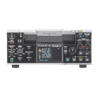
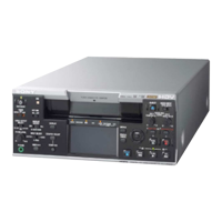
HVR-M25J/M25U/M25N/M25E/M25P/M25C
1. Playing Level Check
Mode PLAY
Signal Alignment tape: For audio check
(NTSC: XH5-3/PAL: XH5-3P)
Measurement Point AUDIO OUT terminal (CH-1, 2)
Measuring instrument Audio level meter
Oscilloscope
Specified Value 32 kHz mode section:
1 kHz signal must be outputted.
48 kHz mode section:
1 kHz signal level is
+8 to +12 dBs (NTSC)
+6 to +10 dBs (PAL)
44.1 kHz mode EMP ON section:
7.35 kHz signal level is
+2 to +6 dBs (NTSC)
0 to +4 dBs (PAL)
44.1 kHz mode EMP OFF section:
7.35 kHz signal level is
+8 to +12 dBs (NTSC)
+6 to +10 dBs (PAL)
Note: Check that the data of page: 0, address: 10 is “00”.
Checking method:
1) Check that the play signal level satisfies the specified value.
2) Check with the oscilloscope that no clip is found in the output
waveform.
2. Audio Test Signal Level Check
Mode E-E
Signal Audio test signal
Measurement Point AUDIO OUT terminal (CH-1, 2)
Measuring instrument Audio level meter
Oscilloscope
Specified Value –11 to –8.5 dBs
Note 1: 0 dBs = 0.775 Vrms
Switch setting
1) COLOR BAR (IN/OUT REC menu) ................. ON [TONE]
Checking method:
1) Set the 60i/50i SEL (OTHERS menu) to “60i”.
2) Check that the output of AUDIO OUT terminal (CH-1, 2) sat-
isfies the specified value.
3) Check with the oscilloscope that no clip is found in the output
waveform.
4) Set the 60i/50i SEL (OTHERS menu) to “50i”.
5) Check that the output of AUDIO OUT terminal (CH-1, 2) sat-
isfies the specified value.
6) Check with the oscilloscope that no clip is found in the output
waveform.
7) Set the 60i/50i SEL (OTHERS menu) to “50i” or “60i”.
Note 2: 60i: HVR-M25J/M25U/M25N
50i: HVR-M25E/M25P/M25C
 Loading...