EasyManua.ls Logo

Sony HXR-FMU128 User Manual

Sony HXR-FMU128
15 pages
To Next Page IconTo Next Page
Page #1 background imageLoading...
Page #1 background image
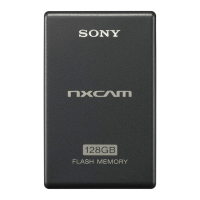
HXR-FMU128
Sony EMCS Co.
SERVICE MANUAL
Revision History
Ver. Date History Contents
SERVICE NOTE (Check the following note before the service.)
985273911.pdf
2009K0500-1
© 2009.11
Published by Tokai TEC
Ver. 1.0 2009.11
FLASH MEMORY UNIT
The components identified
by mark or dotted line with
mark are critical for safety.
Replace only with part number
specified.
Les composants identifiés par
une marque sont critiques
pour la sécurité.
Ne les remplacer que par une
pièce portant le numéro spécifié.
HXR-FMU128
US Model
Canadian Model
AEP Model
Chinese Model
Japanese Model
Official Release2009.111.0
9-852-739-11
1.0
1-1. PRECAUTIONS ON REPLACEMENT OF THE SSD
1-2. PRECAUTIONS ON REPLACEMENT OF THE BOARD
Question and Answer IconNeed help?

Do you have a question about the Sony HXR-FMU128 and is the answer not in the manual?

Sony HXR-FMU128 Specifications

General IconGeneral
BrandSony
ModelHXR-FMU128
CategoryStorage
LanguageEnglish

Summary

Service Notes

SSD Replacement Precautions

Guidelines for safely replacing the Solid State Drive (SSD).

Board Replacement Precautions

Important steps to follow when replacing internal circuit boards.

Safety Warnings and Checks

Critical Component Identification

Identifies critical safety components and replacement requirements.

Post-Repair Safety Checks

Steps to ensure safety and proper function after servicing.

Repair Parts List

Repair Notes and Handling

Important handling instructions for flexible boards and connectors.

Block Diagrams

Overall Block Diagram

High-level overview of the unit's functional blocks and signal flow.

Power Block Diagram

Power Supply Circuitry

Diagram illustrating the power distribution and regulation within the unit.

Schematic Diagrams and Printed Wiring Boards

Schematic Diagrams (Detailed)

ED-063 Board Schematics

Detailed schematic for the ED-063 board, showing pin assignments.

ED-063 Board Schematics (SATA-USB Bridge)

SATA-USB Bridge Component Connections

Detailed pin assignments and connections for the SATA-USB bridge IC.

ED-063 Board Schematics (Power Conversion)

DC/DC Converter Circuit Details

Schematic detailing the DC/DC converter and its associated components.

LDO Regulator Circuit Details

Schematic detailing the LDO regulator and its associated components.

Printed Wiring Board Layouts

ED-063 Board Printed Wiring Layouts

Related product manuals