EasyManua.ls Logo

Sony ICF-C303 - How to Use the Sleep Timer; Setting Sleep Timer Operation

Sony ICF-C303
17 pages
Print Icon
To Next Page IconTo Next Page
To Previous Page IconTo Previous Page
Loading...
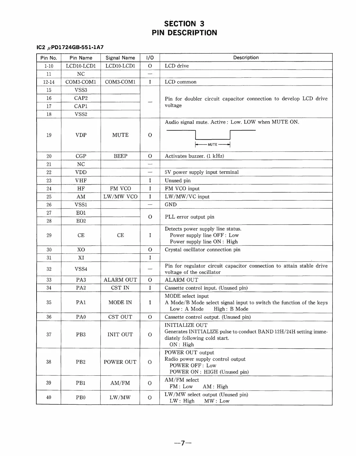
SECTION
3
PIN
DESCRIPTION
IC2
.PD1724GB-551-1A7
LCD10-LCD1
|
LCD10-LCD1
|
O
|
LCD
drive
NC
ee
COM3-COM1
COM3-COM1
LCD
common
Pin
for
doubler
circuit
capacitor
connection
to
develop
LCD
drive
voltage
—
a"
Audio
signal
mute.
Active:
Low.
LOW
when
MUTE
ON.
—_
}-——
MUTE
——»
Activates
buzzer.
(1
kHz)
5V
power
supply
input
terminal
I
Unused
pin
FM
VCO
I
FM
VCO
input
LW/MW
VCO
I
LW/MW/VC
input
—
co
Ro
f
BO
Re
|
Z|8
rs
bo
=
a8
y
i)
wo
DO]
BD]
&
~
ao
>
PLL
error
output
pin
do
co
Detects
power
supply
line
status.
Power
supply
line
OFF:
Low
Power
supply
line
ON:
High
Crystal
oscillator
connection
pin
Pin
for
regulator
circuit
capacitor
connection
to
attain
stable
drive
voltage
of
the
oscillator
ALARM
OUT
ALARM
OUT
Cassette
control
input.
(Unused
pin)
MODE
select
input
MODE
IN
A
Mode/B
Mode
select
signal
input
to
switch
the
function
of
the
keys
Low:
A
Mode
High:
B
Mode
CST
OUT
Cassette
control
output.
(Unused
pin)
INITIALIZE
OUT
Generates
INITIALIZE
pulse
to
conduct
BAND
12H/24H
setting
imme-
diately
following
cold
start.
ON:
High
POWER
OUT
output
Radio
power
supply
control
output
SER
ONS
POWER
OFF:
Low
POWER
ON:
HIGH
(Unused
pin)
AM/FM
select
on
pee
FM:
Low
AM:
High
LW/MW
select
output
(Unused
pin)
iP
L
Pe
NON
LW:
High
MW:
Low
ia
a
ee
La
VDD
Eee
a
|
5
|
26
|
||
|
8
~~)
©
C
ea)
QO
ie)
+}
va
-
oo bo
i
w
_
INIT
OUT