Do you have a question about the Sony ICF-F12S and is the answer not in the manual?
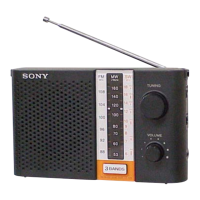
Details the FM, MW, and SW frequency coverage for the radio.
Covers speaker, output, power, dimensions, and mass specifications.
Lists the required DC voltage and battery type.
Lists items included with the radio.
Discusses the use and characteristics of unleaded solder.
Explains the meaning of the lead-free mark on PCBs.
Provides instructions for replacing ceramic filters.
Guides users on how to install batteries correctly.
Offers tips for optimizing radio reception.
Step-by-step guide outlining the sequence for unit disassembly.
Instructions for removing the rear cabinet assembly.
Procedures for accessing and handling the main board and gear mechanism.
Steps for removing the antenna, battery lid, and rear cabinet.
Guidance on setting and aligning the gear mechanism and main board.
Covers Intermediate Frequency (IF) adjustments for MW and SW bands.
Details calibration of MW, SW, and FM frequency coverage.
Explains the fine-tuning process for MW, SW, and FM band reception.
Layout of components and traces on the main board.
Functional block representation of the main integrated circuit.
Detailed electrical schematic for the main board.
Detailed list of all capacitor components used in the device.
Detailed list of all coil components used in the device.
Detailed list of all resistor components used in the device.
Detailed list of all semiconductor components used in the device.
Guidance on identifying differences between original and revised main boards.
Updated diagrams provided in the supplement for the revised main board.
Revised printed wiring board layout specific to the updated main board.
Revised list of electrical parts for the updated main board.
| Type | Portable Radio |
|---|---|
| Tuning | Analog |
| Tuner Bands | FM / AM |
| Frequency Range (FM) | 87.5 - 108 MHz |
| Frequency Range (AM) | 530 - 1710 kHz |
| Output Power | 100 mW |
| Headphone Jack | 3.5 mm |
| Power Source | 2 x AA batteries (not included) |
| Speaker | Built-in |
| Antenna | Built-in telescopic antenna (FM), internal ferrite bar antenna (AM) |