Do you have a question about the Sony ICF-S79 and is the answer not in the manual?
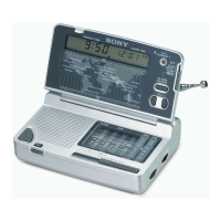
Details radio frequency bands and channel steps for different regions.
Specifies 12-hour or 24-hour system based on model and region.
Details speaker size and impedance.
Specifies power output level with distortion.
Details power source and battery type.
Provides physical measurements of the unit.
Indicates the weight of the unit.
Lists items included with the radio.
Provides initial instructions and model differences.
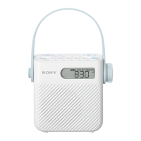
Highlights splash resistance, timer, AUTO OFF, and PLL tuner.
Estimates operating hours with different battery types.
Provides important precautions regarding battery handling.
Instructions for tuning stations manually.
Guide for listening to the weather broadcast band.
Instructions for storing and recalling preset stations.
Step-by-step guide to saving a station to a preset button.
How to use timer functions with preset buttons.
Explains the automatic radio shut-off feature.
Critical warning against submerging the unit in water.
Step-by-step guide to disassembling the rear cabinet.
Procedure for adjusting FM frequency coverage.
Procedure for adjusting FM signal tracking.
Procedure for adjusting LW frequency coverage.
Procedure for adjusting LW signal tracking.
Procedure for adjusting AM (MW) frequency coverage.
Procedure for adjusting AM (MW) signal tracking.
Procedure for adjusting TV frequency coverage.
Procedure for adjusting TV signal tracking.
Procedure for adjusting TV Intermediate Frequency.
Procedure for adjusting AM Intermediate Frequency.
Locations for FM frequency and tracking adjustments.
Locations for AM (MW) frequency and tracking adjustments.
Locations for LW frequency and tracking adjustments.
Locations for TV frequency, tracking, and IF adjustments.
Location for AM IF adjustment.
Layout diagrams of the main and key boards.
Instructions for replacing ceramic filters, including color codes.
Reference table for semiconductor component locations.
Key for understanding printed wiring board markings.
Explanations of symbols and notations used in the schematic.
Indicates signal flow for FM, AM, and LW.
Block diagram for IC1 TA7358P, specific to ICF-S79V.
Detailed pin functions for IC6, the system controller.
Explanation of band select signal logic for BAND1 and BAND2 pins.
List of switches and components for the key board.
List of band pass filter components.
List of capacitors and chip conductors.
List of diodes and chip conductors.
List of integrated circuits used in the device.
| Product color | White |
|---|---|
| Radio type | Clock |
| Tuner type | Analog |
| Number of batteries supported | 3 |