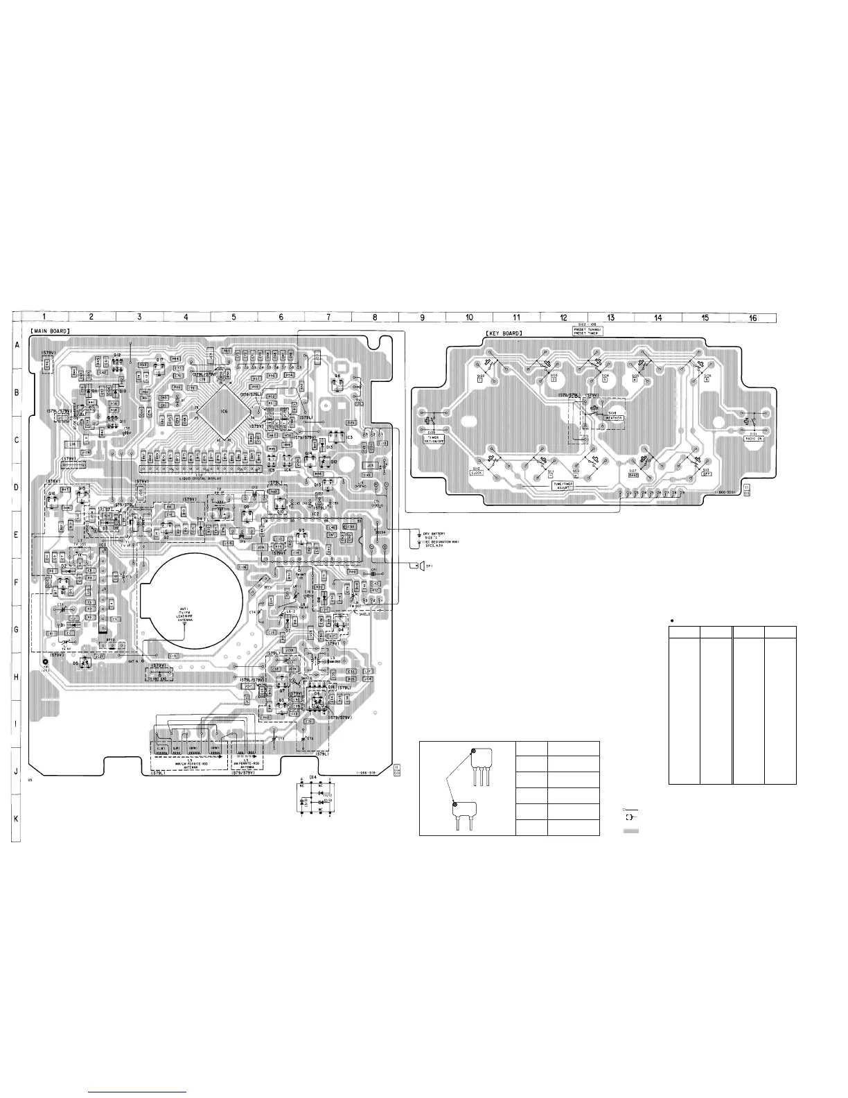
Note on Printed Wiring Board:
• : parts extracted from the component side.
• : indicates side identified with part number.
•
¢
: internal component.
• : Pattern from the side which enables seeing.
– 7 –
– 8 –
ICF-S79/S79L/S79V
Mark Center frequency
red 10.70 MHz
blue 10.67 MHz
orange 10.73 MHz
black 10.64 MHz
white 10.76 MHz
HOW TO CHANGE THE CERAMIC FILTERS
This model is used two ceramic filters of CF1, CF3.
You must use same type of color marked ceramic filters in order to
meet same specifications.
Therefore, the ceramic filter must change two pieces together since
it's supply two pieces in one package as a spare parts.
mark
CF1
CF3
SECTION 4
DIAGRAMS
4-1. PRINTED WIRING BOARDS
Semiconductor Location
D1 G-1 Q1 F-1
D2 F-1 Q2 E-4
D3 E-2 Q3 I-6
D4 E-4 Q4 G-7
D5 H-2 Q5 E-6
D6 H-7 Q6 B-7
D7 G-6 Q7 H-6
D8 F-7 Q9 E-5
D9 E-2 Q10 D-6
D10 B-2 Q11 C-2
D11 B-2 Q12 A-2
D12 C-7 Q13 D-7
D13 C-7 Q14 C-7
D14 H-7 Q15 D-2
Q16 D-1
IC1 F-2 Q17 A-3
IC2 E-7
IC3 C-7
IC4 C-6
IC5 C-6
IC6 B-5
Ref. No. Location Ref. No. Location