EasyManua.ls Logo

Sony ICF-SW1 User Manual

Sony ICF-SW1
28 pages
To Next Page IconTo Next Page
Page #1 background imageLoading...
Page #1 background image
SERVICE
MANUAL
REVISED
/
Circuit
system
Frequency
range
Antennas
Speaker
Power
output
Outputs
Power
requirements
Battery
life
Dimensions
MICROFILM
SPECIFICATIONS
FM:
Superheterodyne
AM:
Dual,
conversion
superheterodyne
FM:
76
108
MHz
(TYPE
1)
87.5
108
MHz
(TYPE
2
to
4)
LW:
150
528
kHz
(TYPE
1
to
3)
150
285
kHz
(TYPE
4)
MW:
531
1,611
kHz
(at
MW
channel
step
selector
set
to
9
kHz)
530
1,610
kHz
(at
MW
channel
step
selector
set
to
10
kHz)
:
SW:
1,615
29,995
kHz
(TYPE
1,
3)
1,615
26,100
kHz
(TYPE
2,
4)
Telescopic
antenna
(FM/SW)
Built-in
ferrite
bar
antenna
(MW/LW)
Active
antenna
(LW/MW/SW)
Approx.
66
x
35
mm
(25/g
inches
x
11/2
inches)
8
ohms
250
mW
(at
10%
harmonic
distortion)
Recording
output
jack
(minijack)
output
level
0.775
mV
(—60
dB)
output
impedance
1
kilohm
Headphone
jack
(stereo
minijack)
for
18
ohm
stereo
earphones
Radio:
3
V
dc
Two
size
AA
(R6)
batteries
Supplied
AC
power
adaptor
(110,
120,
220
or
240
V
ac
adjustable,
50/60
Hz)
Radio:
approx.
12
hours
of
listening
for
four
hours
a
day
at
a
normal
volume,
using
Sony
SUM-3
(NS)
batteries
Approx.
118.2
x
71.4
x
23.7
mm
(w/h/d)
(49/4
x
27
x
1516
inches)
including
projecting
parts
and
controls
Weight
Accessories
supplied
US
Model
Canadian
Model
AEP
Model
UK
Model
E
Model
Australian
Model
Approx.
230
g
(5
Ib
6.5
02)
including
batteries
AC
power
adaptor
(1,
except
for
Australian
model)
Stereo
earphones
(1)
Antenna
controller
(1)
Antenna
module
(1)
Carrying
case
(soft
...
1
hard
...
1)
AC
plug
adaptor
(1,
except
for
UK
model)
Suction
cup
(1)
Carrying
beit
(1)
Wave
handbook
(1)
SAFETY-RELATED
COMPONENT
WARNING!!
COMPONENTS
IDENTIFIED
BY
MARK
A
ON
THE
SCHEMATIC
DIAGRAMS
AND
IN
THE
PARTS
LIST
ARE
CRITICAL
TO
SAFE
OPERATION.
REPLACE
THESE
COMPONENTS
WITH
SONY
PARTS
WHOSE
PART
NUM-
BERS
APPEAR
AS
SHOWN
IN
THIS
MANUAL
OR
IN
SUPPLEMEMTS
PUBLISHED
BY
SONY.
ATTENTION
AU
COMPOSANT
AYANT
RAPPORT
ALA
SECURITE!
LES
COMPOSANTS
IDENTIFIES
PAR
UNE
MARQUE
A\
SUR
LES
DIAGRAMMES
SCHEMATIQUES
ET
LA
LISTE
DES
PIECES
SONT
CRITIQUES
POUR
LA
SECURITE
DE
FONCTIONNEMENT.
NE
REMPLACER
CES
COMPO-
SANTS
QUE
PAR
DES
PIECES
SONY
DONT
LES
NUMEROS
SONT
DONNES
DANS
CE
MANUAL
OU
DANS
LES
SUPPLEMENTS
PUBLIES
PAR
SONY.
FM
STEREO/LW/MW/SW
PLL
SYNTHESIZED
RECEIVER
ONY.
Question and Answer IconNeed help?

Do you have a question about the Sony ICF-SW1 and is the answer not in the manual?

Sony ICF-SW1 Specifications

General IconGeneral
BrandSony
ModelICF-SW1
CategoryRadio
LanguageEnglish

Summary

Safety Component Warning

Section 1 General

Location and Function of Controls

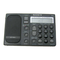
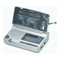
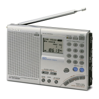
Identifies controls on the front and rear panels of the receiver.

Supplied Accessories

Lists and illustrates the accessories included with the product.

How to Set the Clock

Step-by-step instructions for setting the radio's internal clock.

Direct Tuning

Procedure for tuning to a specific frequency by direct input.

Manual Tuning

Guide to tuning stations using manual increment/decrement.

Scan Tuning

Instructions for automatic station scanning and selection.

Preset Tuning

How to preset stations and tune into them.

Automatic Radio Turn-On

Setting the timer standby function for automatic operation.

Sleep Timer

How to set the sleep timer for automatic radio shutdown.

Active Antenna Usage

Instructions for using the supplied active antenna for better reception.

Section 2 Outline

Outline of the C-MOS Digital-Tuning System

Overview of the IC801, µPD1715G-545 digital tuning system.

Outline of the Station Selection

Details frequency coverages and scan ranges for station selection.

Description on the Terminals

Explains the functions of each terminal on the IC801 chip.

Initial-State Setting

Describes operations performed during initial power-on and backup conditions.

Muting-Output Timings

Details the timing of mute signals during various operations.

Segments and Commons of Liquid-Crystal Display Panel

Shows the segments and commons of the LCD panel.

Relationship of LCD Segments to LSI Pin

Illustrates how LCD segments connect to the LSI pins.

Section 3 Disassembly

Section 4 Electrical Adjustments

AM Section Adjustments

Procedures for AM 1st local and 2nd local/3kHz/5kHz step adjustments.

FM Section Adjustments

Procedures for FM tracking and voltage adjustments.

Section 5 Diagrams

Block Diagram

Schematic representation of the radio's functional blocks.

Semiconductor Lead Layouts

Diagrams showing the pin configurations of semiconductor components.

Circuit Boards Location

Identifies the physical locations of the main circuit boards.

Printed Wiring Boards

Section 7 Electrical Parts List

Section 8 Antenna Module (AN-101)

Supplement-1

ICF-SW1E Model Addition

Information on the ICF-SW1E economy model and its differences.

Accessory and Packing Material

Details accessories and packing materials for ICF-SW1S and ICF-SW1E models.

Supplement-2

AM Frequency Range Change

Notes on AM frequency range changes for West Germany models.

Supplement-3

Exploded Views Update

Provides updated exploded views for specific components.

Related product manuals