Do you have a question about the Sony IJ1001M and is the answer not in the manual?
Highlights key features like long life, safety, quick charge, and scalability.
Lists brackets and screws for controller mounting and attachment.
Lists power connectors and brackets for module mounting and securing.
Lists communication cables, termination connectors, and power cables for system setup.
Explains symbols used in the manual and unit for safety communication.
Guidelines for using designated, undamaged cables and proper connection procedures.
Advises against closed areas, direct sun/heaters, and dusty/humid environments.
Recommends protective gear and warns against water/foreign objects and unauthorized opening.
Emphasizes stable installation, rack fixing, and using designated packaging.
Warns against touching with wet hands, using as a stool, and improper disposal.
Procedures for power off during malfunction and handling liquid leaks from the module.
Prohibits disassembly, modification, medical use, and external object insertion.
Explains control of charge/discharge, display panel, host communication, and protection.
Details charge/discharge control based on signal lines and voltage/temperature conditions.
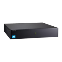
Identifies and describes the LCD display, DISP button, Indicator LED, and Power switch.
Details the rear terminals for communication, power, and external devices.
Explains how to switch display modes and interpret display images.
Details various display fields like status, cell temp, cycle count, and alarm bits.
Identifies and describes front and rear interfaces for modules, including LEDs and switches.
Step-by-step guide for physically mounting the controller and modules in a rack.
Explains connection variations for different controller types (IJ1001C/IJ1002C, IJ4001C).
Details how to connect multiple modules in parallel for increased capacity.
Outlines serial connection for IJ4001C modules to increase voltage.
Describes combining series and parallel connections for IJ4001C modules.
Step-by-step guide for connecting power and communication cables and setting addresses.
Instructions for connecting to a host, grounding, and checking system status.
Procedure for safely powering down the controller and modules.
Details the CC/CV charging curve and recommended voltage/current parameters.
Explains errors related to no module connection and communication errors.
Details errors for Over Voltage and Over Discharge, and their corrective actions.
Lists operating voltage, current, storage temperature, and dimensions for controllers.
Lists capacity, voltage, power, current, temperature, and dimensions for modules.
Information on battery recycling obligations and environmental responsibility.
Contact information for product failure, warranty, and service inquiries.