Do you have a question about the Sony KD-32DX100U and is the answer not in the manual?
Steps for automatic channel tuning.
Instructions on locating video input sources.
How to access information via digital text services.
How to access information via analogue text services.
Guide to using the program index for channel selection.
Settings for audio output, effects, and balance.
Procedure to correct image rotation issues.
Setting a unique ID for personalized TV features.
Procedure for manual analogue channel tuning.
Programming the remote for VCR/DVD control.
Solutions for common TV operational problems.
Initial steps for removing the television's rear cover.
Intermediate steps for rear cover removal.
Final steps for detaching the rear cover.
Procedure to disconnect speaker connectors.
Steps for removing the main chassis assembly.
Orienting the chassis for service access.
Instructions for removing D and G circuit boards.
Procedure for removing the G1 bracket.
Steps to remove the F1 circuit board.
Steps to remove the H1 circuit board.
Steps to remove the N board shield.
Safe procedure for removing the CRT picture tube.
Guidance on removing and refitting bottom plates.
Safety instructions for removing the front glass panel.
Adjusting electron beam alignment for picture centering.
Aligning RGB beams for correct color display.
Steps to adjust picture sharpness for optimal clarity.
Adjusting screen brightness and color temperature.
Detailed electrical calibration procedures via service mode.
Electronic adjustment of audio output levels.
Accessing and utilizing Test Mode 2 for diagnostics.
Overall system connectivity diagram.
Detailed system block diagram section.
Further system block diagram details.
Continuation of system block diagrams.
Additional system block diagram sections.
More system block diagrams.
Final system block diagram sections.
Additional system block diagrams.
Visual guide to identifying circuit board placements.
Detailed circuit schematics and PCB layouts.
Exploded view of KD-32DX100 chassis components.
Exploded view of KD-32DX100 picture tube assembly.
Exploded view of KD-32NS100/32NX100 chassis parts.
Exploded view of KD-32NS100/32NX100 picture tube.
Exploded view of the KD-32NS100B modem accessory.
List of parts for the F3 board of KD-32DX100.
List of parts for the H5 board of KD-32DX100.
List of parts for the H6 board of KD-32DX100.
List of parts for the B4 circuit board.
List of parts for the F board of KD-32DX100.
List of parts common across multiple models.
List of parts specific to certain model variants.
Parts list for KD-32DX100 and KD-32NX100 models.
Parts list for the KD-32NS100 model.
List of parts for the M3 circuit board.
List of parts for the G1 circuit board.
List of parts for the G circuit board.
List of parts for the D circuit board.
List of parts for the VM circuit board.
List of parts for the J1 circuit board.
List of parts for the N1 circuit board.
List of parts for the F1 board (KD-32NS100/32NX100).
List of parts for the H1 board (KD-32NS100/32NX100).
List of parts for the H2 board (KD-32NS100/32NX100).
List of parts for the H3 board (KD-32NS100/32NX100).
List of parts for the L board (KD-32NS100).
Listing of various other parts and items.
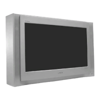
| Screen Size | 32 inches |
|---|---|
| Display Technology | CRT |
| Aspect Ratio | 16:9 |
| Resolution | 1366 x 768 |
| HDMI Ports | 0 |
| USB Ports | 0 |