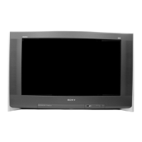
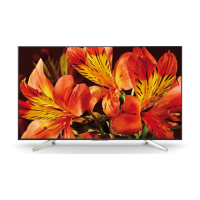
Do you have a question about the Sony KD-32NX100U and is the answer not in the manual?
Table mapping diagnostic item descriptions to LED flash counts and probable causes.
List of error messages and their corresponding LED codes.
Solutions for common picture and sound problems encountered with the TV.
Step-by-step instructions for removing the rear cover of the TV.
Procedure for disconnecting the speaker connector before rear cover removal.
Instructions for removing and refitting the TV chassis assembly.
Procedure for removing the D and G circuit boards.
Detailed steps for removing the picture tube, including anode cap handling.
Procedures for safely removing the anode cap from the picture tube.
Safety instructions for removing the glass panel, requiring two people.
Safety instructions for refitting the glass panel, requiring two people.
Procedure for adjusting beam landing for proper picture alignment.
Steps for adjusting horizontal and vertical static convergence for optimal picture.
How to adjust the focus control on the flyback transformer for best screen focus.
Adjusting G2 control and white balance using service mode.
Performing electrical adjustments using the remote commander in service mode.
Adjusting deflection system parameters to achieve an optimal image.
Table of contents for the electrical parts list, referencing page numbers for each board.
Parts list for the F3 board, specific to the KD-32DX100 model.
Parts list for the A board, specific to the KD-32NS100 model variant.
Parts list for the M3 board, covering various component types.
Parts list for the G1 board, including capacitors, connectors, diodes, ICs, and resistors.
Parts list for the C board, including capacitors, connectors, diodes, ICs, and resistors.
Parts list for the D board, covering resistors, capacitors, and transformers.
| Display Technology | LCD |
|---|---|
| Aspect Ratio | 16:9 |
| Resolution | 1366 x 768 |
| HDMI Ports | 2 |
| USB Ports | 1 |
| Screen Size | 32 inches |
| HDTV Compatibility | HDTV |

