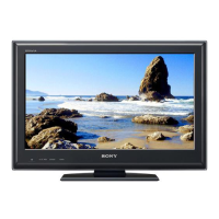
Do you have a question about the Sony KDL-26L5000; KDL-32L5000 and is the answer not in the manual?
| Display Resolution | 1366 x 768 |
|---|---|
| Aspect Ratio | 16:9 |
| Response Time | 8 ms |
| Component Video Input | 1 |
| S-Video Input | 1 |
| Display Technology | LCD |
| Refresh Rate | 60 Hz |
| Screen Size | 26 inches, 32 inches |
| Viewing Angle | 178° |
| Input Ports | HDMI, Component, Composite, S-Video, PC Input |
| Sound Output | 10 W + 10 W |
| PC Input | 1 (D-Sub) |
Guidelines for safe handling of the LCD panel to prevent damage and ensure safety during repair.
Diagram and explanation of the circuit used to measure AC leakage current for safety verification.
Methods and verification steps to ensure a proper earth ground connection for safety testing.
Explanation and circuit diagram for performing AC leakage tests on the TV set.
Explanation of how the STANDBY LED flashes indicate specific error codes and possible causes.
Details the function and color of the POWER, STANDBY, and PIC OFF/TIMER LEDs.
Step-by-step instructions for removing the rear cover of the television unit.
Procedure for removing the switch unit, including disconnecting its connector.
Steps to remove the A Board and G2BE (Power Supply) board, including connector disconnections.
Instructions for removing the table-top stand and under cover from the TV.
Procedure for safely removing the loudspeakers from the TV assembly.
Detailed steps for removing internal brackets and spine components for both models.
Instructions for removing the H2 board and the LCD panel assembly.
Procedure for removing the Balancer (MT Inverter) board for the 26-inch model.
Procedure for removing the Balancer (MT Inverter) board for the 32-inch model.
Diagram illustrating the internal wiring layout and routing for the TV.
Information on accessing and viewing service adjustment data for optimal viewing.
Step-by-step guide to enter the service adjustment mode using the remote commander.
Instructions to restore user controls and channel memory to factory preset conditions.
Diagram showing the physical location of major circuit boards within the TV.
Key for understanding symbols, abbreviations, and notations used in schematics.
Overview of the TV's internal functional blocks and their interconnections.
Detailed circuit diagrams and associated technical information for troubleshooting.
Exploded view and parts list for the rear cover and stand assembly.
Exploded view and parts list detailing the main chassis components.
Exploded view and parts list for the front bezel and LCD panel.
A visual guide and list of screws used in the assembly and disassembly process.
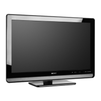
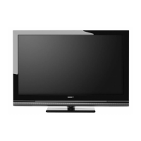

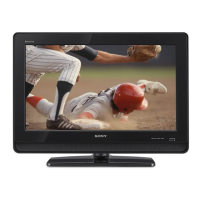
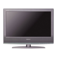


 Loading...