- 9 -
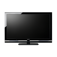
2-1. Rear Cover Removal
SECTION 2 DISASSEMBLY
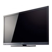
2-2. Stand Assy Removal
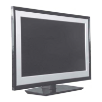
2-3. Under Cover Removal
To remove the ‘Under Cover’ first remove the Rear Cover
(See Sec 2-2-1) and then the Stand Assy (See Sec 2-2-2). The
‘Under Cover’ can then be gently pulled away from the back
of the TV set.
=>
1
2
=>
=>
2
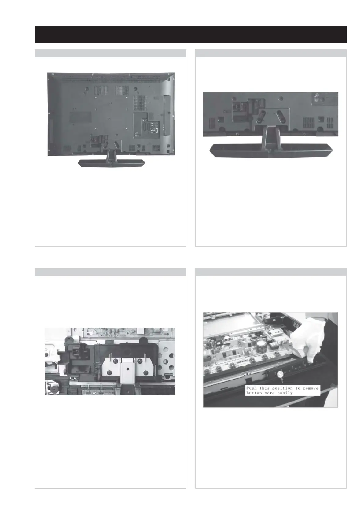
2-4. Switch Unit Removal
=>
1
=>
1
=>
1
=>
1
=>
1
=>
1
=>
1
=>
1
=>
=>
=>
Remove the rear cover fixing screws indicated and pull the
‘Rear Cover’ gently backwards away from the back of the
TV set.
Screw Part number(s) and Description(s)
1) 2-580-640-01 SCREW, +BVTP2 4X16 (32” = 17pcs, 40” = 16pcs)
2) 7-685-648-79 SCREW, +BVTP 3X12 (32/40” = 2pcs)
3) 2-580-600-01 SCREW, +PSW M4X8 (32” = 2pcs)
4) 2-580-602-01 SCREW, +PSW M4X12 (40” = 2pcs)
Remove the 4 stand fixing screws indicated and lift the TV set
up and away from the ‘Stand Assy’.
Screw Part number(s) and Description(s)
1) 2-580-608-01 SCREW, +PSW M5X16
1
1
1
=>
=>
=>
=>
=>
=>
1
=>
1
=>
2
=>
2
3/4
1
3/4
To remove the ‘Switch Unit’ lift the bottom of the bracket
towards the TV set. Push the top of the bracket in the
shaded area in the photograph. The bracket will then
release from its boss and can be removed from the TV set.
=>
1
=>
1
 Loading...