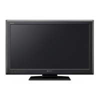
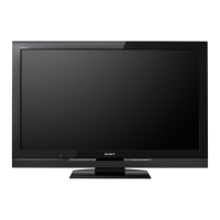
Do you have a question about the Sony KDL-32S5600 and is the answer not in the manual?
Identifies the TV model and designates this document as a service manual.
Records changes made to the service manual over time.
Provides critical safety cautions and warnings for servicing procedures.
Step-by-step guide for removing and refitting the MDF-61 connector.
Instructions for proper harness routing and dressing at connectors.
Details technical specifications for TV system, power, and dimensions.
Tables detailing supported PC and HDMI input signals and timings.
Pinout and signal assignments for SCART, HDMI, and PC connectors.
Lists LED flash codes, error descriptions, checked status, and actions.
Step-by-step guides for removing major internal components.
Guide to accessing and using service menus for adjustments.
Explanation of TT modes and how to access them.
Overall block diagram of the TV's electronic system.
Diagrams showing circuit board placement and schematic symbols.
Detailed electrical schematics for the B board (parts 1-12).
Schematic diagram for the H1 board's IR and LED functions.
Schematic diagram for the IP1F power supply (parts 1-2).
Visual guides showing component placement on printed circuit boards.
Comprehensive lists of all electrical components with part numbers.
Comprehensive list of components for the B board (capacitors).
Comprehensive list of components for the H1 board (transistors, resistors).
Lists accessory parts and connectors for different models.
| Display diagonal | 32 \ |
|---|---|
| Display brightness | - cd/m² |
| Display technology | LCD |
| Native aspect ratio | 16:9 |
| Viewable size diagonal | 82 mm |
| Contrast ratio (dynamic) | 33000:1 |
| Plug and Play | Yes |
| Placement supported | Horizontal |
| Headphone connectivity | 3.5 mm |
| Favorite pages quantity | 2000 pages |
| RGB ports quantity | 1 |
| USB 2.0 ports quantity | USB 2.0 ports have a data transmission speed of 480 Mbps, and are backwards compatible with USB 1.1 ports. You can connect all kinds of peripheral devices to them. |
| Product color | Black |
| Panel mounting interface | 200 x 200 mm |
| Power consumption (sleep) | 0.3 W |
| RMS rated power | 10 W |
| Number of speakers | 2 |
| Depth (with stand) | 222 mm |
|---|---|
| Width (with stand) | 807 mm |
| Height (with stand) | 557 mm |
| Depth (without stand) | 94 mm |
| Height (without stand) | 508 mm |