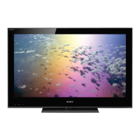
Do you have a question about the Sony KDL-40XBR4 and is the answer not in the manual?
Details power requirements, consumption, and specifications for various input/output interfaces.
Guidelines for safe handling, carrying the TV, and general service cautions.
Highlights critical safety components and replacement procedures.
Describes LED indicators and how they signal diagnostic error codes for troubleshooting.
Instructions and diagrams for removing the rear cover for specific models.
Instructions and warnings for removing the inverter board and its cover.
Overview of remote buttons and procedures to enter and navigate service menus for adjustments.
Diagrams showing board layout and explanations of schematic symbols and notations.
Illustrates system block diagrams and connector pin assignments for different models.
Exploded view and parts list for the rear cover and stand assembly.
Exploded views and parts list for bezel assembly, LCD panel, and related screws.
List of capacitors for the AU board, including part number, description, and values.
| Screen Size | 40 inches |
|---|---|
| Display Type | LCD |
| Backlight Type | CCFL |
| Aspect Ratio | 16:9 |
| Refresh Rate | 120 Hz |
| Response Time | 8 ms |
| HDMI Ports | 3 |
| USB Ports | 1 |
| Component Video Inputs | 2 |
| Composite Video Inputs | 1 |
| S-Video Inputs | 1 |
| PC Input | 1 |
| Viewing Angle | 178 degrees |
| Resolution | 1920 x 1080 |
| Audio Output | 1 (RCA) |





 Loading...