EasyManua.ls Logo

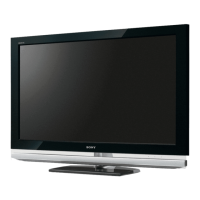
Sony KDL-40XBR6 User Manual

Sony KDL-40XBR6
107 pages
To Next Page IconTo Next Page
Page #1 background imageLoading...
Page #1 background image
LCD DIGITAL COLOR TELEVISION
SERVICE MANUAL
EX1
CHASSIS
MODEL NAME REMOTE COMMANDER DESTINATION
9-883-802-01
KDL-40XBR6
RM-YD024 US/CND
KDL-40XBR6
RM-YD024 MX/LATIN AMERICA
KDL-46XBR6
RM-YD024 US/CND
KDL-46XBR6
RM-YD024 MX/LATIN AMERICA
KDL-52XBR6
RM-YD024 US/CND
KDL-52XBR6
RM-YD024 MX/LATIN AMERICA
HISTORY INFORMATION FOR THE FOLLOWING MANUAL:
ORIGINAL MANUAL ISSUE DATE: 8/2008
REVISION DATE SUBJECT
8/2008 No revisions or updates are applicable at this time.

Table of Contents

Question and Answer IconNeed help?

Do you have a question about the Sony KDL-40XBR6 and is the answer not in the manual?

Sony KDL-40XBR6 Specifications

General IconGeneral
BrandSony
ModelKDL-40XBR6
CategoryLCD TV
LanguageEnglish

Summary

History Information

Specifications

Warnings and Cautions - English

Warnings and Cautions - French

Safety Warnings and Precautions

Safety-Related Component Warning

Warning about critical components affecting safety and their replacement.

Use Caution When Handling the LCD Panel

Precautions to take when handling the LCD panel to avoid damage.

Safety Check-Out Procedure

Self-Diagnostic Function Overview

Section 1: Disassembly Procedures

1-1. Rear Cover and Switch Unit Removal

Procedure for removing the rear cover and switch unit.

1-2. Woofer Box Removal

Instructions for removing the woofer box assembly.

1-3. Board Removal (AWF, BU, G, D)

Steps for removing AWF, BU, G, and D circuit boards.

1-4. Table-Top Stand and Under Cover Removal

Procedure for removing the table-top stand and under cover.

1-5. Structural Frames, Brackets and AC Inlet Removal

Steps for removing structural frames, brackets, and AC inlet.

1-6. Speaker Cover and Speaker Box Removal

Instructions for removing the speaker cover and speaker box.

1-7. H3R Board and H4R Board Removal

Procedure for removing the H3R and H4R circuit boards.

1-8. LCD Panel, Illumination Module and Logo Holder Removal

Steps for removing the LCD panel, illumination module, and logo holder.

1-9. Inverter Board Removal

Instructions for removing the inverter board.

Wire Dressing Information

Information regarding wire dressing diagrams, provided separately.

Section 2: Service Adjustments and Data

2-1. Viewing Service Adjustment Data

Information on viewing service adjustment data for optimal viewing.

2-2. Accessing Service Adjustment Mode

Procedure to enter the service adjustment mode using the remote commander.

2-3. Viewing the Service Menus

How to navigate and view different service menus.

2-4. Using Remote Commander for Service Data

Instructions for using the remote to view and adjust service data.

2-5. Resetting to Factory Defaults

Procedure to restore user controls and channel memory to factory settings.

Section 3: Diagrams and Schematics

3-1. Circuit Boards Location

Diagram showing the location of various circuit boards within the TV.

3-2. PWB and Schematic Information

Information on interpreting schematic diagrams and PWB layouts.

3-3. Block Diagram

Overall functional block diagram of the television's systems.

3-4. Schematics and Supporting Information

Detailed schematic diagrams and supporting technical information.

3-5. Semiconductors Identification

List and diagrams of semiconductor components used in the TV.

Section 4: Exploded Views and Parts

4-1. Rear Cover and Table-Top Assembly

Exploded view of the rear cover and table-top stand assembly.

4-2. Chassis (KDL-40XBR6/46XBR6 Only)

Exploded view of the chassis for 40/46 inch models.

4-3. Chassis (KDL-52XBR6 Only)

Exploded view of the chassis for the 52 inch model.

4-4. Connectors (KDL-40XBR6/46XBR6 Only)

Diagrams and list of connectors for 40/46 inch models.

4-5. Connectors (KDL-52XBR6 Only)

Diagrams and list of connectors for the 52 inch model.

4-6. Bezel and LCD Panel (KDL-40XBR6/46XBR6 Only)

Exploded view of the bezel and LCD panel for 40/46 inch models.

4-7. Bezel and LCD Panel (KDL-52XBR6 Only)

Exploded view of the bezel and LCD panel for the 52 inch model.

4-5. Screw Legend

Legend for screws used in disassembly and assembly.

Section 5: Electrical Parts List

Appendix A: Encryption Key Components

Related product manuals