EasyManua.ls Logo

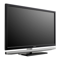
Sony KDL-40XBR9 User Manual

Sony KDL-40XBR9
118 pages
To Next Page IconTo Next Page
Page #1 background imageLoading...
Page #1 background image
LCD DIGITAL COLOR TELEVISION
SERVICE MANUAL
EX2M
CHASSIS
MODEL NAME REMOTE COMMANDER DESTINATION
9-883-821-03
KDL-40XBR9
RM-YD029 US/CND
KDL-40XBR9
RM-YD029 MX/LATIN AMERICA
KDL-46XBR9
RM-YD029 US/CND
KDL-46XBR9
RM-YD029 MX/LATIN AMERICA
KDL-52XBR9
RM-YD029 US/CND
KDL-52XBR9
RM-YD029 MX/LATIN AMERICA
HISTORY INFORMATION FOR THE FOLLOWING MANUAL:
ORIGINAL MANUAL ISSUE DATE: 4/2009
: UPDATED ITEM
REVISION DATE SUBJECT
4/2009 No revisions or updates are applicable at this time.
5/2009 Added section 2-4. Setting the Destination After Replacing the BU Board. Replaced page 43.
Corrected BU Board Part Numbers for Mexico and Latin America models. Replaced page 82 & 87.
9/2009 Updated Exploded View Section to remove LCD Panel specifi c information. Replaced page 85.

Table of Contents

Question and Answer IconNeed help?

Do you have a question about the Sony KDL-40XBR9 and is the answer not in the manual?

Sony KDL-40XBR9 Specifications

General IconGeneral
BrandSony
ModelKDL-40XBR9
CategoryLCD TV
LanguageEnglish

Summary

SECTION 1: DISASSEMBLY

1-1. Rear Cover Removal

Procedures for removing the rear cover for specific models.

1-3. BU Board, Inverter Board, and Power Board Removal

Steps to remove BU, Inverter, and Power boards.

1-7. LCD Panel, Illumination Module, HL5 Board, and Heat Sink Removal

Procedure for removing LCD panel, illumination module, and heat sink.

SECTION 2: SERVICE ADJUSTMENTS

2-2. Accessing Service Adjustment Mode

Steps to access the service adjustment mode via the remote.

2-4. Setting the Destination After Replacing the BU Board

Procedure to set the correct destination after BU board replacement.

SECTION 3: DIAGRAMS

3-3. Block Diagram

Overall system block diagram illustrating major functional units and connections.

3-5. Schematics and Supporting Information

Detailed schematic diagrams for various boards, including BU, D1N, D2N, etc.

SECTION 4: EXPLODED VIEWS

4-1. Rear Cover Assembly and Table-Top Stand Assembly

Exploded view of the rear cover and table-top stand assembly.

4-5. Bezel Assembly and LCD Panel

Exploded view of the bezel assembly and LCD panel.

SECTION 5: ELECTRICAL PARTS LIST

CAPACITOR

List of all capacitors with part numbers, values, and specifications.

RESISTOR

List of all resistors with part numbers, values, and specifications.

TRANSISTOR

List of all transistors with part numbers and specifications.

DIODE

List of all diodes with part numbers and specifications.
IC

List of integrated circuits with part numbers and specifications.
Related product manuals