Do you have a question about the Sony KLV-32D300A and is the answer not in the manual?
Details on brightness, contrast, viewing angle, resolution, color gamut, motion response, and sound.
Table detailing PC input signal resolutions, frequencies, and standards.
Servicing instructions for qualified personnel to reduce electric shock risk.
Critical parts must be replaced with specified part numbers to prevent hazards.
Precautions for safely handling and repairing the LCD panel to avoid damage.
Procedures and limits for measuring AC leakage current from exposed metal parts to earth ground.
Methods to identify a reliable earth ground connection for safety testing.
STANDBY LED flash counts indicating possible causes of problems and error conditions.
Visual representation of STANDBY LED flash patterns and their meaning.
Method to disable the STANDBY LED error flashing by turning off the unit.
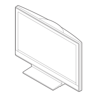
Procedures for removing the rear cover and stand/VESA arm for 32D300A/32V300A.
Steps for removing H1, U1/U2, G1H, BG1/UT, BH boards, and DTT shield.
Instructions for removing speakers, under cover, and LCD panel assembly.
Procedures for removing the rear cover and stand/VESA arm for 40/46 series.
Steps for removing various boards, shields, and covers for 40/46 series.
Instructions for removing speakers, H3/H4, D2/D3 boards, and LCD panel assembly.
Diagrams showing the location of various circuit boards within the TV models.
| Screen Size | 32 inches |
|---|---|
| Resolution | 1366 x 768 pixels |
| Display Type | LCD |
| HD Technology | HD Ready |
| Aspect Ratio | 16:9 |
| HDMI Ports | 2 |
| USB Ports | 1 |
| Brightness | 450 cd/m² |
| Response Time | 8 ms |
| Viewing Angle | 178 degrees |
| VGA Port | Yes |
| Connectivity | HDMI, USB, Composite |
| Sound Output | 20 W (10W x 2) |
| Audio Output | 10W x 2 |