EasyManua.ls Logo

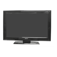
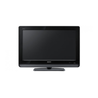
Sony KLV-32BX300 User Manual

Sony KLV-32BX300
39 pages
To Next Page IconTo Next Page
Page #1 background imageLoading...
Page #1 background image
LCD DIGITAL COLOR TV
SERVICE MANUAL
AZ1-A
CHASSIS
MODEL NAME REMOTE COMMANDER DESTINATION
9-883-845-51
KLV-32BX300
RM-YD035 AR
KLV-32BX300
RM-YD035 LATIN AMERICA
KLV-40BX400
RM-YD035 AR
KLV-40BX400
RM-YD035 LATIN AMERICA
LEVEL
3
CONFIDENTIAL
HISTORY INFORMATION FOR THE FOLLOWING MANUAL:
ORIGINAL MANUAL ISSUE DATE: 3/2010
REVISION DATE SUBJECT
3/2010 No revisions or updates are applicable at this time.
Question and Answer IconNeed help?

Do you have a question about the Sony KLV-32BX300 and is the answer not in the manual?

Sony KLV-32BX300 Specifications

General IconGeneral
Screen Size32 inches
Resolution1366 x 768
Display TypeLCD
HDMI Ports2
USB Ports1
BacklightCCFL
Component Video Input1
Composite Video Input1
Aspect Ratio16:9
Refresh Rate50 Hz

Summary

Safety-Related Component Warnings

LCD Panel Handling Precautions

Guidelines for safely handling LCD panels during repair to prevent damage.

Leakage Current Hot Check Circuit

Description of the circuit used for checking AC leakage current in the device.

Safety Check-Out Procedures

Earth Ground Verification

Method for identifying and confirming a reliable earth ground connection.

AC Leakage Testing

Detailed steps for performing AC leakage tests on the television set.

Section 1: Diagrams

Circuit Boards Location

Visual guide showing the physical placement of circuit boards within the TV chassis.

Schematic Diagram Conventions

Explains notations, symbols, and conventions used in schematic diagrams.

Reference Information

Semiconductor Terminal Identification

Identifies terminal names for semiconductors as displayed on silk screen prints.

Block Diagram

Schematics and Supporting Information

BAA Board Schematic: Input Section

First part of the BAA board schematic, detailing input and initial signal paths.

BAA Board Schematic: HDMI/Tuner Section

Second part of the BAA board schematic, covering HDMI and tuner interfaces.

BAA Board Schematic: Audio Section

Third part of the BAA board schematic, focusing on audio processing circuits.

BAA Board Schematic: MICON Section

Fourth section of the BAA board schematic, illustrating the MICON and control interfaces.

BAA Board Schematic: Power Section

Fifth section of the BAA board schematic, detailing power supply and voltage regulation circuits.

BAA Board Schematic: DDR Section

Sixth section of the BAA board schematic, showing the DDR memory interface connections.

BAA Board Schematic: Main 1 Section

Seventh section of the BAA board schematic, covering main system logic (part 1).

BAA Board Schematic: Main 2 Section

Eighth section of the BAA board schematic, detailing main system logic (part 2).

BAA Board Schematic: LVDS/Panel Section

Ninth section of the BAA board schematic, illustrating the LVDS and panel interface.

BAA Board Component Layout: Component Side

BAA Board Component Layout: Conductor Side

G2HE Board Schematic Diagram (KLV-40BX400 Only)

G2HE Power Section Component Side (KLV-40BX400 Only)

G2HE Power Section Conductor Side (KLV-40BX400 Only)

G2LE Board Schematic Diagram (KLV-32BX300 Only)

G2LE Power Section Component Side (KLV-32BX300 Only)

G2LE Power Section Conductor Side (KLV-32BX300 Only)

H2LR Board Schematic Diagram

H2LR IR/LED Section Component Side

H2LR IR/LED Section Conductor Side

H2LS Board Schematic Diagram

Section 2: Electrical Parts List

BAA Board Complete (KLV-32BX300 Only)

Complete list of electrical parts for the BAA board for KLV-32BX300 model.

BAA Board Complete (KLV-40BX400 Only)

Complete list of electrical parts for the BAA board for KLV-40BX400 model.

G2HE Board Complete (KLV-40BX400 Only)

G2LE Board Complete (KLV-32BX300 Only)

H2LR Board Mounted

H2LS Board Mounted

Appendix A: Encryption Key Components

Related product manuals