EasyManua.ls Logo

Sony KLV-40V300A User Manual

Sony KLV-40V300A
45 pages
To Next Page IconTo Next Page
Page #1 background imageLoading...
Page #1 background image
5B6E056B0DBC8C3EA98124D4035F0D2DAA0CF7903190433B6D69139D7A3D7F60AB45BB781B1BB606
Ver. DATA CONTENTS
1.0 2007.06 Issued
1.1 2007.07 Addition of KLV-32D300A/40D300A/46D300A models.
(P. 4 , P. 5, P. 1-1, P. 2-1, P. 3-1)
1.2 2007.12 Addition of KLV-40V380A/46V380A models.
(P. 1 , P. 6, P. 1-7, P. 2-1, P. 3-8)
1.3 2008.02 Correction of disassembly for SEC 1. (P. 1-9)
Correction of circuit boards location for SEC 2. (P. 2-1)
Correction of part number for SEC 3. (P. 3-11)
MODEL NAME : KLV-32/40/46D300A, 32/40/46V300A, 40/46V380A
SERVICE MANUAL
PA RTS No. : 9-834-157-04
MODIFICATION HISTORY
* Blue characters are linking.
Question and Answer IconNeed help?

Do you have a question about the Sony KLV-40V300A and is the answer not in the manual?

Sony KLV-40V300A Specifications

General IconGeneral
BrandSony
ModelKLV-40V300A
CategoryTV
LanguageEnglish

Summary

MODIFICATION HISTORY

SPECIFICATIONS

PC Input Signal Reference Chart

WARNINGS AND CAUTIONS

Use Caution When Handling the LCD Panel

Safety guidelines for handling the LCD panel during repair.

SAFETY CHECK-OUT

Leakage Test

Procedure to check for AC leakage current from metal parts to earth ground.

How to Find a Good Earth Ground

Methods to establish a reliable earth ground connection for testing.

SELF DIAGNOSIS FUNCTION

1-1. Diagnostic Test Indicators

Explanation of STANDBY LED flash codes to identify problem causes.

1-2. Display of Standby/Timer Light Flash Count

Visual representation of STANDBY LED flash counts and their meaning.

1-3. Stopping the Standby Flash

Instructions on how to disable the STANDBY LED error flash indication.

1-4. Self-Diagnostic Screen Display

How to view past error occurrences on the screen for diagnosis.

1-5. Quitting Self-diagnostic Screen

Procedure to exit the self-diagnostic screen mode.

SECTION 1 DISASSEMBLY

1-1. KLV-32D300A/32V300A Disassembly

Detailed disassembly procedures for KLV-32 models.

1-2. KLV-40/46D300A, 40/46V300A, 40/46V380A Disassembly

Detailed disassembly procedures for KLV-40/46 models.

SECTION 2 DIAGRAMS

2-1. Circuit Boards Location

Diagrams illustrating the placement of circuit boards within the TV.

SECTION 3 EXPLODED VIEWS

3-1. KLV-32D300A/32V300A Exploded Views

Exploded diagrams and part listings for KLV-32 models.

3-2. KLV-40/46D300A, 40/46V300A, 40/46V380A Exploded Views

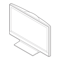
Exploded diagrams and part listings for KLV-40/46 models.

3-3. Packing Materials (KLV-32D300A/32V300A)

List and diagrams of packing materials for KLV-32 models.

3-4. Packing Materials (KLV-40D300A/40V300A/40V380A)

List and diagrams of packing materials for KLV-40 models.

3-5. Packing Materials (KLV-46D300A/46V300A/46V380A)

List and diagrams of packing materials for KLV-46 models.

Related product manuals