EasyManua.ls Logo

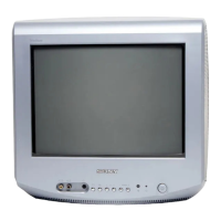
Sony KV-14LM1E User Manual

Sony KV-14LM1E
42 pages
To Next Page IconTo Next Page
Page #1 background imageLoading...
Page #1 background image
1
SERVICE MANUAL
FE-2
CHASSIS
MODEL
COMMANDER DEST CHASSIS NO.
KV-14LT1B
RM-887 French SCC-Q54B-A
KV-14LT1E
RM-887 Spanish SCC-Q53B-A
KV-14LT1K
RM-887 OIRT SCC-Q51B-A
KV-14LT1U
RM-887 UK SCC-Q52B-A
MODEL
COMMANDER DEST CHASSIS NO.
KV-14LM1B
RM-889 French SCC-Q54D-A
KV-14LM1E
RM-889 Spanish SCC-Q53D-A
KV-14LM1K
RM-889 OIRT SCC-Q51D-A
KV-14LM1U
RM-889 UK SCC-Q52D-A
RM-889
Question and Answer IconNeed help?

Do you have a question about the Sony KV-14LM1E and is the answer not in the manual?

Sony KV-14LM1E Specifications

General IconGeneral
BrandSony
ModelKV-14LM1E
CategoryTV
LanguageEnglish

Summary

FE-2 SELF DIAGNOSTIC SOFTWARE

Switching On the TV and Automatically Tuning

Introducing and Using the Menu System

Menu Guide

Explains the navigation and functions of the on-screen menu system.

Teletext and Optional Equipment

Specifications and Troubleshooting

SECTION 2 DISASSEMBLY

Rear Cover and Board Removal

Steps for removing the rear cover and A Board PWB.

Service Position and Wire Dressing

Procedures for positioning the unit and managing wires during service.

Picture Tube Removal

Procedure for safely removing the picture tube.

SECTION 3 SET-UP ADJUSTMENTS

Beam Landing

Adjusting beam landing for picture quality.

Convergence

Adjusting color convergence for picture clarity.

Geometry and Screen Adjustments

Covers various geometric and screen convergence adjustments.

Focus and White Balance Adjustment

Adjusting focus, screen brightness (G2), and white balance.

SECTION 4 CIRCUIT ADJUSTMENTS

Electrical Adjustments

Performing electrical adjustments via service mode.

TEST MODE 2

Using Test Mode 2 for various TV functions.

SECTION 5 DIAGRAMS

Circuit Board Location and Schematics

Identifying circuit board locations and viewing schematic diagrams.

BLOCK DIAGRAMS

Overview of the TV's functional block diagrams.

SEMICONDUCTORS

List and details of semiconductor components.

IC BLOCK DIAGRAMS

Block diagrams for integrated circuits.

SECTION 6 EXPLODED VIEWS

CHASSIS

Exploded view of the TV chassis assembly.

PICTURE TUBE

Exploded view of the picture tube assembly.
SECTION 7 ELECTRICAL PARTS LIST

Related product manuals