Do you have a question about the Sony KV-14LT1E and is the answer not in the manual?
Guides users through initial TV setup, language selection, and channel tuning.
Explains how to navigate and use the TV's on-screen menu for various settings.
Details how to access and use the teletext information service.
Instructions for connecting external devices like VCRs and decoders to the TV.
How to select and view content from connected external devices.
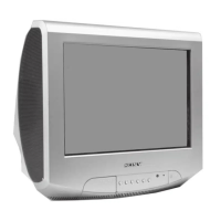
Lists detailed TV system, sound output, power, and dimension specifications.
Provides solutions for common picture and sound problems.
Step-by-step guide for safely removing the TV's rear cover.
Instructions for removing internal circuit boards (A Board).
How to position the chassis for servicing and manage internal wiring.
Detailed procedures for safely removing the CRT picture tube.
Adjusts the alignment of electron beams for optimal picture geometry.
Aligns the Red, Green, and Blue electron beams for accurate color display.
Corrects picture shape, pincushion, and corner distortions.
Adjusts horizontal line linearity and height.
Adjusts vertical and horizontal positioning and size.
Corrects convergence issues at the screen corners using magnets.
Optimizes the sharpness and clarity of the picture.
Adjusts screen brightness and color temperature for accurate white balance.
Performs internal electrical adjustments via the service mode.
Details various test modes and their functions accessible via the remote.
Identifies the physical location of circuit boards within the TV.
Provides circuit schematics and printed wiring board layouts.
Illustrates the functional blocks and signal flow within the TV.
Lists part numbers for semiconductor components used in the TV.
Shows the internal logic and pin functions of integrated circuits.
Diagram showing the assembly of the TV's main chassis components.
Diagram illustrating the assembly of the CRT picture tube unit.
Lists all parts associated with the C Board assembly.
Lists common parts used across multiple A Board variants.
Lists parts specific to different A Board model variants.
Lists general components like speakers, antennas, and power cords.
Lists included accessories, manuals, and packaging items.
Lists parts for the remote control units.
| Screen Size | 14 inches |
|---|---|
| Display Technology | CRT |
| Aspect Ratio | 4:3 |
| TV Standard | PAL, SECAM |
| Resolution | Unknown |
| Inputs | SCART, RF |