Do you have a question about the Sony KV-29LS30E and is the answer not in the manual?
| Screen Size | 29 inches |
|---|---|
| Display Type | CRT |
| Aspect Ratio | 4:3 |
| TV Standard | PAL, SECAM |
| Sound System | NICAM Stereo |
| Teletext | Yes |
| Sound Output | 20 W |
| Input Ports | Scart, RF |
| Audio Output | 20W (10W x 2) |
Step-by-step guide for powering on the TV and performing automatic channel tuning.
Explains how to navigate and use the TV's on-screen menu system for adjustments.
Instructions on accessing and viewing teletext information services.
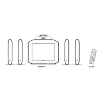
Guide on connecting external devices like VCRs and other AV equipment.
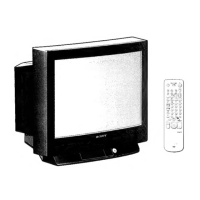
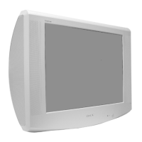
Detailed technical specifications for the KV-29LS30 and KV-29LS35 models.
Provides solutions for common problems related to picture and sound.
Procedures for removing the rear cover and disconnecting speaker components.
Guidance on removing the main chassis and specific PWB (Printed Wiring Board) modules.
Detailed steps for safely removing the CRT picture tube, including anode cap handling.
Adjusting beam landing and purity for optimal picture geometry.
Procedures for horizontal and vertical static convergence adjustment.
Steps for adjusting picture focus and white balance for accurate color reproduction.
Guide to accessing service mode and performing various electrical adjustments.
Explains functions available in Test Mode 1 using specific remote commands.
Details functions and access for Test Mode 2, including menu navigation.
Visual representation of the TV's internal circuitry and signal flow.
Identifies the physical locations of the main circuit boards within the TV.
Detailed electronic schematics and PCB layouts for repair.
List and diagrams of semiconductor devices used in the chassis.
Functional block diagrams for key integrated circuits used in the TV.
Illustrated diagram showing chassis components and their assembly order.
Exploded view of the picture tube assembly and associated parts.