EasyManua.ls Logo

Sony KV-32FX60D User Manual

Sony KV-32FX60D
92 pages
To Next Page IconTo Next Page
Page #1 background imageLoading...
Page #1 background image
1
SERVICE MANUAL AE-5 CHASSIS
MODEL
COMMANDER DEST CHASSIS NO.
MODEL
COMMANDER DEST CHASSIS NO.
KV-28FX60A
RM-891 Italian SCC-Q12D-A
KV-28FX60B
RM-891 French SCC-Q13D-A
KV-28FX60D
RM-891 AEP SCC-Q11D-A
KV-28FX60E
RM-891 Spanish SCC-Q14D-A
KV-28FX60K
RM-891 OIRT SCC-Q16F-A
KV-28FX60R
RM-891 OIRT SCC-Q16E-A
KV-28FX60U
RM-891 UK SCC-Q15C-A
KV-32FX60A
RM-891 Italian SCC-Q12B-A
KV-32FX60B
RM-891 French SCC-Q13B-A
KV-32FX60D
RM-891 AEP SCC-Q11B-A
KV-32FX60E
RM-891 Spanish SCC-Q14B-A
KV-32FX60K
RM-891 OIRT SCC-Q16A-A
KV-32FX60R
RM-891 OIRT SCC-Q16B-A
KV-32FX60U
RM-891 UK SCC-Q15B-A
®
MICROFILM
TRINITRON
®
COLOR TV
Question and Answer IconNeed help?

Do you have a question about the Sony KV-32FX60D and is the answer not in the manual?

Sony KV-32FX60D Specifications

General IconGeneral
Screen Size32 inches
Display TypeCRT
Aspect Ratio4:3
TV StandardPAL/SECAM
Power Consumption150 W
Audio Output20W (10W x 2)

Summary

First Time Operation

Step 1 Installation

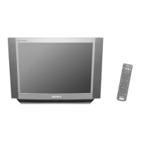
Connecting the TV set and inserting batteries into the remote control.

Step 2 Basic Presetting

Guide to menu system, language, country, and automatic channel tuning.

Advanced Operation

Advanced Operation Topics

Advanced TV Operation

Advanced TV Operation Features

Teletext

AE-5 Self-Diagnostic Software

Diagnostic Item Description

Description of diagnostic items, LED flashes, probable causes, and symptoms.

Error Count Table

Table listing error codes and their corresponding LED error counts.

Error Detection Monitor

Error Monitor Menu

Display of operating time and saved/actual errors.

Error Reader Display

Send Data to Error Reader

Table mapping error codes to data and error types for the reader.

SECTION 2 DISASSEMBLY

SECTION 2 DISASSEMBLY Continued

SECTION 2 DISASSEMBLY Continued Further

Picture Tube Removal

Procedure for removing the picture tube.

SECTION 2 DISASSEMBLY Final

SECTION 3 SET-UP ADJUSTMENTS

3-1. Beam Landing

Adjusting the correction magnet for Y-splitting axis.

3-2. Convergence

Roughly adjusting focus and horizontal convergence.

3-3. Focus

Adjusting the focus control on the flyback transformer.

3-4. White balance

Adjusting G2 control and backend settings for optimal white balance.

SECTION 3 SET-UP ADJUSTMENTS Continued

3-4. Screen (G2), White Balance

Adjusting G2 control and backend settings for optimal white balance.

SECTION 4 CIRCUIT ADJUSTMENTS

4-1. ELECTRICAL ADJUSTMENTS

Performing service adjustments using the Remote Commander RM-891.

4-2. VOLUME ELECTRICAL ADJUSTMENTS

Sub Colour Adjustment

Adjusting Sub Colour data for waveform height.

4-3. TEST MODE 2

SECTION 5 DIAGRAMS Continued

SECTION 6 EXPLODED VIEWS

SECTION 6 EXPLODED VIEWS Continued

Related product manuals