EasyManua.ls Logo

Sony KV-32FX60E User Manual

Sony KV-32FX60E
92 pages
To Next Page IconTo Next Page
Page #1 background imageLoading...
Page #1 background image
1
SERVICE MANUAL AE-5 CHASSIS
MODEL
COMMANDER DEST CHASSIS NO.
MODEL
COMMANDER DEST CHASSIS NO.
KV-28FX60A
RM-891 Italian SCC-Q12D-A
KV-28FX60B
RM-891 French SCC-Q13D-A
KV-28FX60D
RM-891 AEP SCC-Q11D-A
KV-28FX60E
RM-891 Spanish SCC-Q14D-A
KV-28FX60K
RM-891 OIRT SCC-Q16F-A
KV-28FX60R
RM-891 OIRT SCC-Q16E-A
KV-28FX60U
RM-891 UK SCC-Q15C-A
KV-32FX60A
RM-891 Italian SCC-Q12B-A
KV-32FX60B
RM-891 French SCC-Q13B-A
KV-32FX60D
RM-891 AEP SCC-Q11B-A
KV-32FX60E
RM-891 Spanish SCC-Q14B-A
KV-32FX60K
RM-891 OIRT SCC-Q16A-A
KV-32FX60R
RM-891 OIRT SCC-Q16B-A
KV-32FX60U
RM-891 UK SCC-Q15B-A
®
MICROFILM
TRINITRON
®
COLOR TV
Question and Answer IconNeed help?

Do you have a question about the Sony KV-32FX60E and is the answer not in the manual?
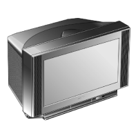
Sony KV-32FX60E Specifications

General IconGeneral
Screen Size32 inches
Display TypeCRT
Aspect Ratio4:3
TV StandardPAL, SECAM
TunerAnalog
Audio Output20 W
ConnectivitySCART

Summary

AE-5 Self-Diagnostic Software

Error Detection Monitor

Service Safety Precautions

General Safety Warnings

Cautions about short circuits, isolation transformers, and safety-critical components.

First Time Operation and Basic Presetting

Advanced Operation: Presetting Channels

Advanced TV Operation: Picture and Sound

Teletext Operations

SECTION 2 DISASSEMBLY

Picture Tube and Anode Cap Handling

Steps for removing the picture tube assembly and safely handling the anode cap.

SECTION 3 SET-UP ADJUSTMENTS

Beam Landing Adjustment

Setting up beam landing and purity using correction magnets.

Convergence Adjustments

Adjusting convergence settings for screen centre using H.STAT and V.STAT.

SECTION 4 CIRCUIT ADJUSTMENTS

Electrical Adjustments: Service Mode Entry

How to enter the service mode using the remote commander and navigate menus.

Test Mode 2 Operations

Operating the TV using Test Mode 2 functions and available options.

5-2. CIRCUIT BOARD LOCATION

SECTION 6 EXPLODED VIEWS

6-2. PICTURE TUBE Exploded View and Parts

SECTION 7 ELECTRICAL PARTS LIST

Related product manuals