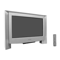
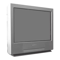
Do you have a question about the Sony FD Triniton KV-32FQ75D and is the answer not in the manual?
Learn to tune channels, find video inputs, sort programs, and manage channel settings.
Utilize program guides, Teletext, and navigate menus for TV features and settings.
Configure advanced settings like program presets, demo mode, and picture geometry adjustments.
Step-by-step guide for disassembling the TV, including chassis and board removal.
Safely remove the picture tube and anode cap, including high-voltage discharge procedures.
Procedures for removing front control modules, specific circuit boards, and internal component access.
Adjust beam landing, purity, and convergence for optimal picture alignment and color accuracy.
Adjust focus for picture sharpness and white balance for accurate color reproduction.
Access and perform electrical adjustments via the service mode using the remote commander.
Utilize Test Mode 2 for diagnostics and access error logs via the error monitor.
Identify circuit board locations and understand system architecture via block diagrams.
Detailed schematic diagrams and printed wiring board layouts for technical analysis.
Visual breakdown of chassis and picture tube assemblies with part references.
Detailed list of all electrical parts, organized by board and model for easy identification.
Identify TV errors through LED flashes and understand diagnostic codes for troubleshooting.
Key technical specifications of the TV, including system, power, and dimensions.
Solutions for common picture and sound problems encountered during TV operation.
Guide to using the TRACE tool for TV repair, covering interface setup and software functions.
| Display Technology | CRT |
|---|---|
| Screen Size | 32 inches |
| Aspect Ratio | 4:3 |
| Comb Filter | 3D Digital Comb Filter |
| Speakers | 2 |
| Remote Control | Yes |
| Inputs | Composite, S-Video |
| Color System | NTSC |




 Loading...