Do you have a question about the Sony FD Triniton KV-28FQ75A and is the answer not in the manual?
Guides on powering on, automatic, and manual channel tuning.
Instructions for using NexTView (EPG) and Teletext services.
How to adjust picture settings like contrast, brightness, and sound.
Procedures for re-arranging channels and naming them.
Details on Demo mode, presets, picture rotation, and other features.
Solutions for common picture and sound problems.
Steps to remove the rear cover and disconnect internal cables.
Instructions for removing specific circuit boards like D1, J, and B3.
Safe method for removing the picture tube and anode cap.
Procedure for removing main bracket bottom plates for internal access.
Adjusting beam landing, purity magnets, and Y-splitting axis.
Performing static convergence for color dot alignment.
Adjusting focus control and white balance for optimal picture quality.
Accessing service mode and performing electrical adjustments.
Using LED flashes and error codes for system diagnostics.
Displaying and understanding error messages from the monitor.
Utilizing specific functions within Test Mode 2 for diagnostics.
Visual overview of the TV's internal circuitry and signal flow.
Identifying physical locations of circuit boards within the TV chassis.
Detailed circuit diagrams and component placement on PWB.
Illustrated breakdown of chassis components with part numbers.
Illustrated breakdown of the picture tube assembly and parts.
Comprehensive list of electronic components and their part numbers.
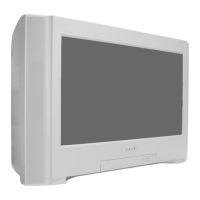
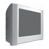
| Screen Size | 28 inches |
|---|---|
| Display Type | CRT |
| Screen Type | Flat |
| Aspect Ratio | 4:3 |
| Audio Output | 20 W |
| Teletext | Yes |
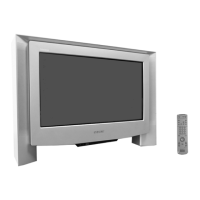
| Remote Control | Yes |
| SCART Inputs | 2 |
| S-Video Input | Yes |
| Component Video Input | No |
| Tuner | Analog |
| Sound Output | 20W |
| Speaker | 2 |
| Input Ports | S-Video |